
Contact us today:
(847) 934-4500
tdaro@bernardandcompany.com
Contact us today:
(847) 934-4500
tdaro@bernardandcompany.com
 REP Corporation, the longtime leader in injection presses for rubber and TPE molding, announces the start of a new credit program, effective immediately and running through July 31, 2010. Molders who validate the scrapping of their older presses can earn up to $40,000 in credit against the purchase of any new REP machine, during this period. The announcement was made today by REP President Tim Graham, at the company’s Bartlett, Illinois headquarters, near Chicago.
Graham detailed the offer, saying it would apply to any make or model of rubber or TPE injection press. REP requires the molder to validate the scrapping of their old machine, thereby earning a predetermined credit, based on the old machine’s age and condition. The credit, up to $40,000, can then be applied to the purchase of any new REP injection press in the G9 series.
He further noted the advantages of a new machine. “Besides the higher quality parts a molder can produce, owing to the level of mold mechanics, material flow and control sophistication, a new press consumes less energy, has less downtime and less maintenance requirements, so it stays in production. Even REP presses from our earlier generations cannot match the productivity and resulting profitability of a new G9 machine. That’s not a brag, it’s a fact and it’s one we can document,” he said, noting the new machines offer better molding strategies, improved ergonomics and faster payback for the customer.
“It’s an offer you can’t refuse,” Graham joked.
REP Corporation is responsible for all sales and service in North America. However, this offer is being made to rubber molders worldwide by REP, based in Lyon, France.
For more information, please contact: REP CORPORATION 8N470 Tameling Court Bartlett, IL 60103-8146 Phone: 847-697-7210 Fax: 847-697-6829 Web: www.repinjection.com Email: tgraham@repcorp.com Attention: Tim Graham, President
PR agency contact: Tim Daro Bernard & Company 847-934-4500 tdaro@bernardandcompany.com
Continue reading No. 945 is an electrically-heated 500°F(~260°C) universal oven from Grieve, currently used for various curing tasks at the customer’s facility. Workspace dimensions are 54” wide x 36” deep x 36” high. 6.6 KW are installed in Nichrome wire heating elements to heat the load, while a 600 CFM, 1/2-HP recirculating blower provides horizontal front to rear airflow.
The unit has 4” insulated walls, an aluminized steel exterior and Type 430 stainless steel interior. It is also equipped with an integral leg stand with casters and leveling pads.
Controls onboard No. 945 include a digital indicating temperature controller, manual reset excess temperature controller with separate contactors, recirculating blower airflow safety switch and SCR power controller.
For more information, please contact: THE GRIEVE CORPORATION, 500 Hart Road, Round Lake, Illinois 60073-2835 USA. Phone: (847) 546-8225. Fax: (847) 546-9210. Web: www.grievecorp.com. Email: sales@grievecorp.com. Attention: FrankCalabrese.
NEWS RELEASE: THE GRIEVE CORPORATION Agency contact: Tim Daro 847-934-4500
DATE: March 22, 2010
Continue reading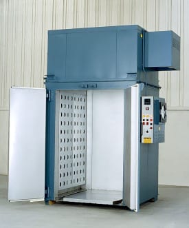 No. 813 is a gas-heated 500°F(~260°C) walk-in oven from Grieve, currently used for curing printed circuit boards. 350,000 BTU/HR is installed in a modulating natural gas burner and workspace dimensions are 48” wide x 48” deep x 72” high.
The unit has 4” insulated walls and an aluminized stainless steel interior and exterior. A 3300 CFM, 2-HP recirculating blower provides horizontal airflow to the oven. Safety equipment, such as a 325 CFM 1/3 powered force exhauster, is included as required by the IRI, FM and the National Fire Protection Association Standard 86 for gas-fired equipment. The oven also features a 2” insulated floor with truck wheel guide tracks and a removable top-mounted heat chamber.
Controls onboard No. 813 include a recirculating blower airflow safety switch, circular chart temperature controller and a manual reset excess temperature controller.
For more information, please contact:
THE GRIEVE CORPORATION
500 Hart Road
Round Lake, Illinois 60073-2835
USA
Phone: (847) 546-8225
Fax: (847) 546-9210
Web: www.grievecorp.com
Email: sales@grievecorp.com
Attention: Frank Calabrese
When the Las Vegas based Cirque de Soleil show, “KA” was looking to maximize motion control and improve the reliability of their stage’s movements, they turned to Siemens. Siemens drives and controls create the automation needed to provide the safety and reliability that is required for a performance of this caliber.
For three years, a Siemens engineering team worked to make this $220 million dollar show and theatre at the Las Vegas MGM Grand spectacular. Visually, the show is like nothing you have ever seen before but reliability, flawless motion and safety was Siemens’ main objective.
The Cirque de Soleil show “KA” requires a 25 x 50 ft section of the floor to rise out of the main portion of the stage. This 6 ft thick, 80 thousand pound
section of the stage provides full motion that rotates 360º and tilts 100º to become a sheer vertical, ultimately lining up perpendicular to the stationary part of the stage… with the performers still on it! I’ll keep my job, thank you. I think Bernard & Company needs to take a field trip to Vegas to see this in person.Check out this video and see how Siemens’ contribution makes this stage show possible.
This article details Siemens’ part in the three year process to get the “KA” stage operating flawlessly.
Complete Set of Application-Ready “Tools” for Converting Applications
ATLANTA — Siemens Industry, Inc. announced today the introduction of the Converting Toolbox, a set of standardized automation tools for the integration of various machine components that previously had to be performed individually. It simplifies web processing applications and offers greater flexibility for machine designers and builders of paper, film, foil and other converting machinery. It is completely scalable and is provided at no cost to qualified machine designers, builders and integrators.
The Converting Toolbox enables machine builders to achieve considerably faster time to market by reducing the time required for engineering, programming, commissioning and documentation, as much as 80 percent in some cases. It offers modular open functions, for items such as:
The Converting Toolbox components take the form of pre-programmed functions. Sample applications demonstrate how each function can be efficiently and effectively implemented into a machine design. Such sample applications are ready-to-use after only minor modifications and include basic HMI functionality. This enables the machine function to be tested and optimized in a very short time frame.
When a functionality module needs to be modified, extended or changed, the Converting Toolbox’s completely open source code provides a wide and solid basis from which even the most specialized functions can be implemented quickly and easily.
Simotion®, the Siemens motion control system, is ideally suited as an operating platform for the Converting Toolbox because applications can be operated directly on an intelligent drive, very compactly and without need of an additional PLC. Simotion offers drive, controller and PC-based topologies. The Converting Toolbox also includes drives-based solutions using Siemens Sinamics® Drive Control Chart (DCC) graphical programming language.
For specific product information and inquiries, call (800) 879-8079 ext. Marketing Communications or send an e-mail to: SiemensMTBUMarCom.industry@siemens.com.
Continue reading
 ATLANTA — Siemens Industry, Inc. announced today a new service for its popular line of 1FK7 servomotors. Using a configurable options menu to build exactly the motor required, customers can now place an order for any Siemens 1FK7 servomotor and have it drop-shipped in three weeks. Thanks to the diverse range of options available, this new service applies to over 100,000 possible configurations. All compact (CT) and high-dynamic (HD) servomotors in the 1FK7 family are included.
With a total of 6150 option pairings and 18 color choices, servomotors in the 1FK7 family can be configured to 110,700 possible designs. Options include stall torque and RPM rating, encoder style and bit resolution, holding brake functionality, shaft style, IP rating, AC line supply voltage and electronic nameplate recognition via Drive-Cliq®. 1FK7 geared motor options are not included in this program.
Siemens is making this service available to customers in the U.S. market. With the motion controller Simotion® and the drive system Sinamics® S stocked in the United States, Siemens is now able to supply complete motion control systems in three weeks’ lead time.
According to Arun Jain, general manager, Siemens Motion Control Business, “We have made the commitment to significantly shorten servomotor delivery times. The 1FK7 family has a wide user base for motion control applications, so we have selected this very important line for this major customer service initiative. We have devised and implemented an entirely new protocol for motor manufacturing and production at our factories.”
For more information, visit www.usa.siemens.com/motioncontrol.
For specific product information and inquiries, call (800) 879-8079 ext. Marketing Communications or send an e-mail to: SiemensMTBUMarCom.industry@siemens.com.
Continue reading

Zimmermann FZ42 portal milling machine with five-axis, five-sided cutting capability
By using a Zimmermann FZ42 portal milling center, Volvo gets the power and torque needed to cut engine fan cases plus the accuracy to turn the machine tool into a coordinate measuring machine for inspection of finished parts
Located near Hartford, Conn., Volvo Aero Connecticut specializes in the machining of large components: fan cases for aircraft engines and gas turbines, fan and compressor structures, compressor rotors, low-pressure turbine cases (LPT) and military parts, usually from aluminum and titanium, as well as Inconel and Waspaloy. It currently manufactures the largest fan casing in the world, at 3.5 meters (11.5 feet) in diameter, for the massive GE90, the only aircraft engine in existence providing 127,900 pounds of thrust, to power the Boeing 777 line. Volvo Aerospace also produces numerous titanium fan cases for Rolls Royce engines.
With the large workpieces, high material removal rates and challenging geometries inherent in aerospace metals manufacturing, coupled with substrates that are often difficult to machine, such as titanium, there is always a need for powerful machining with superior accuracy. Such conditions present substantial hurdles at aerospace supply companies, as they seek to maintain that delicate balance between these seemingly opposing concepts.
As part of its program for the GEnx engine, to be used on the Boeing 787 Dreamliner, Volvo Aero Connecticut recently added a Zimmermann FZ42 machine tool, a five-axis, five-side portal milling center, to its already impressive manufacturing cells at the Hartford facility. The new machine joins other five-axis mills, vertical turning machines, four-axis machining centers and a deburring robot.
Key features on the FZ42 that led Volvo Aero Connecticut to make this acquisition included:

GE90 engine; Volvo Aero Connecticut made the fan casing, currently the largest of its kind at 3.5m (11.5 foot) diameter
In addition, this FZ42 carries a high accuracy package that provides optimum temperature control of the structural machine parts through the use of a special fiber-reinforced compound in the massive side columns. Also facilitating this process are built-in cooling ducts in the portal and Z-axis slide, independent cooling circuits for the A-axis, C-axis and spindle, ground surfaces on the guideways for the Z-axis and side columns, plus a double-pitch measuring system on the A-axis and C-axis.
During the course of manufacturing, thermal expansion of both machine components and workpieces can substantially impact the positioning accuracy of the machine, the stability of the workpiece and the resulting effect on the finished part dimensions. This unique combination of temperature control and mechanical accuracy in the machine construction were an important deciding factor for Volvo Aerospace in acquiring the FZ42.
According to Martin Thorden, engineering manager at Volvo Aero Connecticut, “These features, combined with the onsite machine set-up provided by Zimmermann, were very important to us, especially on this new GEnx project.” Thorden further noted the importance of the control on the machine, a Sinumerik 840D CNC from Siemens. “We see a very big benefit in how well we are able to control the tool with the CNC. We have been able to use the control to take on additional tasks that were previously handled by our CAD/CAM system.” Specifically, he cited the unconventional approach Volvo Aerospace took in machining the big fan cases. They installed the machine without a rotary table, thus realizing over $500,000 in direct cost savings plus material handling time. As a result of that decision, they believed they needed a top-of-the-line control to probe and accurately machine all the features on the part.

Volvo Aero Connecticut, located near Hartford, comprises three buildings, the largest being 40,000 square feet, where various aerospace and military aircraft components are typically produced from aluminum, titanium, Inconel and Waspaloy.
After machining, Volvo Aero Connecticut can actually transition the machine tool into a coordinate measuring machine for inspection, according to Thorden, owing to the superior accuracy provided by the CNC, as well as the special 90 degree angle heads supplied with the machine, part of the MuST® spindle technology from Zimmermann.
Onboard the machine tool, a massive 120-position tool carriage holds various HSK63 and HSK100 tools that are used to machine the substrates worked here. Inside a series of four side stations, within the machine workspace, four additional specialty tools are stored and used for various operations in the machining and measuring process.
All motors and the drive package onboard the Zimmermann FZ42 at this Volvo Aero Connecticut facility are also made by Siemens.
In a typical machining sequence, the milling head on this machine, equipped with the Zimmermann MuST® spindle system, provides Volvo Aerospace numerous other advantages, according to Martin Thorden. All roughing and subsequent finish passes on any material can be achieved in one set-up, which reduces the preparation time and overall production costs by as much as 10%. There is also no need for additional machines and the corresponding materials handling time. The head design further enables Volvo Aero Connecticut to perform tasks other than milling, using the specialty heads stored on the side stations. Changing the spindle, instead of the milling head, enhances repeatability and further reduces the company’s spindle interface costs, according to Thorden.
The combination of increased accuracies, reduced equipment needs and faster throughput has highlighted this Zimmermann machine installation at Volvo Aero Connecticut.
For additional product information and inquiries:
Zimmermann Inc.
Phone: 248-305-9707
Web: www.zimmermann-inc.com
Email: Matthias@zimmermann-inc.com
Attention: Matthias Tockook
Volvo Aero Connecticut
Phone: 860-667-8502
Web: www.volvoaero.com
Email: Martin.Thorden@volvo.com
Attention: Martin Thorden
Siemens Machine Tool Business
John Meyer
Manager, Marketing Communications
Siemens Industry, Inc.
(847) 640-1595
www.usa.siemens.com/cnc
SiemensMTBUMarCom.industry@siemens.com
Follow us on Facebook: www.facebook.com/SiemensCNC or Twitter: www.twitter.com/siemens_cnc_us.
—
Siemens Industry Sector is the world’s leading supplier of innovative and environmentally friendly products, solutions and services for industrial customers. With end-to-end automation technology and industrial software, solid vertical-market expertise, and technology-based services, the sector enhances its customers’ productivity, efficiency and flexibility. With a global workforce of more than 100,000 employees, the Industry Sector comprises the Industry Automation, Drive Technologies and Customer Services Divisions as well as the Metals Technologies Business Unit. For more information, visit http://www.usa.siemens.com/industry.
The Siemens Drive Technologies Division is the world’s leading supplier of products, systems, applications, solutions and services for the entire drive train, with electrical and mechanical components. Drive Technologies serves all vertical markets in the production and process industries as well as the infrastructure/energy segment. With its products and solutions, the division enables its customers to achieve productivity, energy efficiency and reliability. For more information, visit http://www.usa.siemens.com/drivetechnologies.
Continue reading Using Siemens servo controls package and mechatronics service, retrofitter transforms printing press for Ovid Bell
Located in Effingham, Ill., B&L Machine & Design specializes in the remanufacturing of various printing presses and ancillary equipment. Its particular expertise is on the Harris M-1000 and M-110 series presses, as well as splicers, infeeds, chillers and folders. By redesigning all the electrical and mechanical components and subsystems, B&L exceeds customer expectations for the increased set-up, changeover and print speeds demanded by today’s publishing industry, while saving substantial capital for commercial printing companies.
Ovid Bell Press in Fulton, Mo. specializes in print runs from 5,000 to 125,000 copies and works for a variety of multi-color magazine and journal publishers. Recently, B&L needed to help this customer perform shorter-run production work as well as meet the critical make-ready time reductions. Make-ready, in this case, is defined as the period from deceleration after a print run through the time required to remove components as well as the set-up configuration from the previous job. It also covers the installation of new components and set-up on the next job and, finally, the time needed to accelerate the press back up to adequate speed and production of the new forms, all with comparable print quality. A productive press under these short-run conditions must have faster changeover times than traditional presses in the commercial sector, where the runs are considerably longer.
According to Jim Strange, manufacturing manager and electrical engineering supervisor at B&L, “I would say that the shaftless printing implementation on this particular Harris M-1000 press was the biggest part of our challenge. We had determined a shaftless design was the best solution to provide the flexibility of options needed for our core base of printing equipment, in order to compete in this new short run arena.” Strange explained that the press infeed system was converted to a belt drive, eliminating the need for gear trains and oil baths. All the web tension controls were moved to the servo motion processor, thereby further reducing component count.
 B&L redesigned the entire gear train, from a standard line shafted unit, to accept dual motor servo control. By doing this, over 60 components were eliminated by a circumferential register control for all new motor mounts, plate and blanket gearing and servo positioning. The engineers, both mechanical and electrical, at B&L also produced an accurate and reliable plate loading system that enabled plate changes in a fraction of the time required on shafted presses, while leaving the web stationary on the press. This was made possible by the accuracy and flexibility of the servo drive system, according to Strange.
Finally, the folder section of the press was rotated, creating a smaller footprint and improving the folder use, which enabled this customer to install another similar press that can feed either the existing folder or new one. This solution created a more flexible pressroom for better response to market conditions and job flow.
To help with this conversion, B&L contacted three of the largest suppliers of servo control systems for its industry. Each candidate was supplied a press layout, specifics on each piece of required equipment and print quality goals needed to achieve a successful project. A 30-day window was allotted for proposals. When all the proposals had been received and reviewed, the project was awarded to Siemens. Larry Hines, president and owner of B&L, attributed this decision to the vendor’s design assistance, technical competence, service support and current installed base on similar equipment.
The Siemens solution included a Simotion D445 motion controller, Sinamics S120 drives and 1PH7 servo motors. B&L utilized the Simotion Shaftless Standard, a pre-configured application that implements the basic operations for a coordinated motion system and includes rudimentary HMI screens. This software is provided at no charge and saves a great number system engineering hours.
An all-servo design enabled B&L to eliminate drive lines and gave this remanufacturer considerable flexibility in the reconfiguration of existing equipment. Rod Davidson, senior mechanical engineer for B&L, said, “The servo drives enabled us to redesign the entire infeed, and we integrated an absolute encoder to control web tension for smoother operation. Furthermore, the servo drives in the print units let us remove a large number of existing components. Being able to access all the motor position information and scale it to our needs made it easy to build intelligent HMI screens for setting up the phasing, plate positioning and register control.” Finally, he noted the servo drive in the chill unit facilitated further reduction of component count and simplified belt drive configurations. All the mechanical and electrical reconfiguration was accomplished without the need for costly clutch components, according to Davidson.
 “The make-ready time was the area most affected by the servo system. It was cut by at least 50 percent,” said Jim Strange. “The servo system provides the accuracy we required to make the overall process work with dependable, repeatable results.” He also commented that the servo-controlled circumferential register control increased the press accuracy and provided savable print more quickly. Scrap reduction savings have been in the 20 percent range, as well as a corresponding time savings achieved by a faster time-to-good print output.
Overall install time on the press was cut by over 25 percent, due to less drive line construction required, while manufacturing time was reduced by 20 percent, thereby benefiting B&L and its customer alike.
Mechatronics Identifies Problem During Commissioning, Helping Customer Complete Project
During the commissioning process on this Ovid Bell printing press rebuild at B&L, a mechatronics analysis and optimization protocol was conducted by Razvan Panaitescu, engineering manager for mechatronics standards and regulations at Siemens, working in tandem with his Siemens counterparts in application engineering and installation. Mechatronics is the integration of electronics and mechanical engineering, relating to the performance or the design of equipment and machinery. Razvan Panaitescu is a leading authority in this discipline for Siemens.
A problem had surfaced during the test runs on the rebuilt shaftless Harris M-1000 offset press, involving an out of tolerance registration issue. The registration points were visibly oscillating, and the cause was initially thought to lie with the controllers or drives installed as part of the new Siemens product suite onboard.
However, Panaitescu and his team determined the problem resulted from gaps between both the plate and blanket cylinders on the press. When the controllers were finely tuned in a damping optimal setting of higher integrator times and lower proportional gains, the print quality was significantly improved and the registration problems seemed to subside. Not convinced the goal had yet been met, Panaitescu did further vibration testing. A thorough vibration and modal analysis was conducted, using the sophisticated instruments of the Siemens Mechatronics department. The problem was still evident, though to a lesser degree. As he explained, “A resonant frequency remained detectable and that led us to believe there were further mechanical problems in the gear train on two print units, as both continued to reflect unacceptable vibration conditions.” The suggestion was made to check the mechanical accuracy of the gear train and possibly the gear teeth dimensions.
As Panaitescu mused, “Just as a doctor uses the stethoscope on patients, we listen to the drives and press cylinders. From our analysis, we determined the mesh frequency was indicating a sprocket/gear problem.”
In the end, it was determined by B&L and its supplier that an off-normal angle bore on a gear and sprocket assembly was indeed the root cause of the registration problems. Replacements were installed and the press is running well, the result of the mechatronics applied here.
For more information on this story, please contact:
SIEMENS INDUSTRY, INC.
Drive Technologies — Motion Control
390 Kent Avenue
Elk Grove Village, IL 60007
Phone: 847-640-1595 Fax: 847-437-0784
Web: www.usa.siemens.com/motioncontrol
Email: SiemensMTBUMarCom.industry@siemens.com
Attention: John Meyer, Manager, Marketing Communications
OR
B&L Machine & Design
Phone: 217-342-3918
Fax: 217-342-2081
Web: http://www.blmachinedesign.com
Email: lhines@blmachinedesign.com
Attention: Larry Hines, President/Owner

Model TL 6015 Tube Cutting Laser System
Automated loading and parts handling system complement state-of-the-industry laser and machine control technology
Han-Kwang USA announces immediate availability of its new Model TL 6015, a tube cutting laser system capable of handling 24’ long, 6.5” diameter workpieces up to 1/4” wall thickness in mild steel and 0.200” in stainless steel. Equipped with a powerful 2.5KW Panasonic laser and a versatile Siemens 840D CNC to control all functions of the machine, the TL 6015 can significantly increase the tube production in any department or shop, especially when used with Han-Kwang’s proprietary “Flex 3D” tube cutting software . The unit comprises an automatic bundle loading system with tube V-support, auto-centering rotary chucking system, laser cutting station and automatic parts removal station.
Maximum positioning speed on this new laser system is 4700 ipm for the X-

Han-Kwang S5 Cutting Head, featuring Auto Focus Control; adjusts focal length of cutting lens to automatically compensate for material variations and rapid changeover
axis and 120 rpm for the rotary A-axis. Max acceleration rate is 1G, while the laser beam is precisely controlled by the unique Han-Kwang Auto Focus Control (AFC). This AFC technology allows the machine to automatically adjust the focal length of the cutting lens to accommodate variations in the materials being processed or changes in material feed, which eliminates the downtime normally associated with manual adjustments.
A new generation of sensing board in the S5 laser cutting head on the TL 6015 translates into faster cutting speeds on round, square or rectangular shapes.
In a recent design modification, the entire loading section of the machine has been enclosed, as depicted in the attached illustration.
For more information or to arrange a demonstration, please contact:
HAN-KWANG USA INC. Phone: 630-916-0200 Web: www.hankwang.com
Agency contact: Tim Daro Bernard & Company tdaro@bernardandcompany.com www.bernardandcompany.com
Continue reading—–Original Message—–
From: Tim Daro (Bernard & Company)
Sent: Mon 15/02/2010 14:47
To: Jon W (BMW Oracle Racing)
Cc: Fred Young (Forest City Gear); Wendy Young (Forest City Gear); Nicole Zermatten (Bernard & Company); Wendy McCormick (Bernard & Company)
Subject: Congratulations!
We all welcomed the news of your success in winning the Cup.
And the story on Forest City Gear is popping up all over the trade press, here in the States.
Good news, all around!
Thanks for your help, Jon. Enjoy the victory.
Tim
—–Original Message—–
From: Jon W (BMW Oracle Racing)
Sent: Mon 15/02/2010 14:47
To: Tim Daro (Bernard & Company)
Cc: Fred Young (Forest City Gear); Wendy Young (Forest City Gear); Nicole Zermatten (Bernard & Company); Wendy McCormick (Bernard & Company)
Subject: Congratulations!
Hi guys,
I don’t think we could’ve written a better script! The victory will carry the article a bit further for you I’m sure. It was incredible to pick up the America’s Cup last night. I’ve been chasing it for more than 10 years!
Bye for now.
Jon
Check out our press release on FCG and BMW Oracle teaming up.
Go to our Facebook page to see more pictures of the BMW Oracle.
Continue reading