
Contact us today:
(847) 934-4500
tdaro@bernardandcompany.com
Contact us today:
(847) 934-4500
tdaro@bernardandcompany.com
The future of mobility requires sustainability and comfort. Gehring presented its advanced technology solutions for reducing CO2 emissions at a recent technical forum in Querétaro, Mexico.
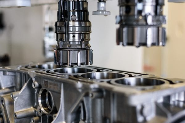 Farmington Hills, Michigan. The future development impetus of the internal combustion engine will focus on the reduction of emissions. This is dependent on fuel consumption, which in turn is determined by the internal engine friction. The goal of form honing is a form optimized cylinder bore under operating conditions.
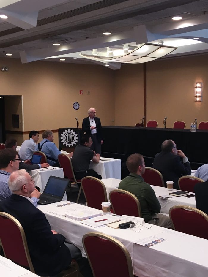
Abraham Pizano, Managing Director Gehring-Mexico, presented Gehring’s CO2 emissions reducing technology solutions at a recent technical forum CO2 in Mexico to an audience of leading technical and business professionals, from a wide variety of industries, including automotive, aerospace and industrial.
The conference is one of the region’s top technical events for manufacturing, featuring the latest in global manufacturing trends, including processes, applications, materials and advanced techniques.
Gehring developed a surface finishing process for ICE’s which does not target a cylindrical bore shape. The bore shape is based on the distortions of the geometry under operating conditions of the engine. Through the means of form honing the reverse shape will be produced so that in running conditions, a cylindrical shape exists. The deformation in the operating condition depends on static assembly distortions and thermal cylinder distortions.
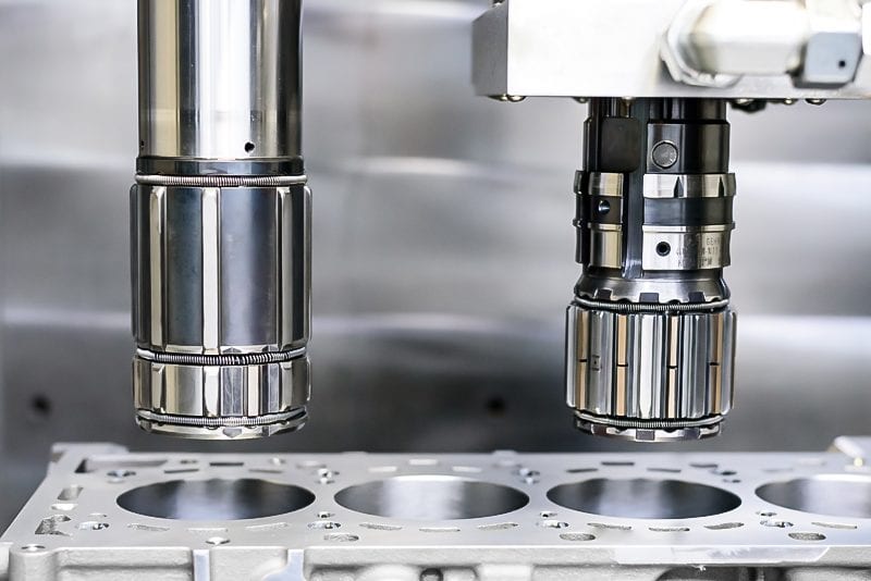 This technology can be subdivided into two process variations, form honing light and form honing professional. Form honing light simulates thermal distortion by creating different tapered shapes. The thermal expansion due to the higher taper in the top dead center leads to a cylinder bore which has to be honed to a smaller size at the top and a larger size at the bottom. Thus, the piston shirt has less contact with the bore. This results in significantly less friction.
The conical shape is generated by feedback controlled stroke displacement with higher stock removal in the lower bore section due to increased contact time of the abrasives.
The dynamic electro-mechanical feeding changes the radial expansion position of the honing stones during the stroke movement according to the form and improves herewith the previous conical shape.
These process components assure the reliable process of round non-cylindrical tapered bores within the known cycle times. Form honing has been already integrated globally into mass production scenarios. Application of form honing light technology has shown that significant improvements in emissions reductions are possible.
Form honing professional not only optimizes the local piston clearance, but also compensates for cylinder deviations from static and thermal distortions. That means that in running conditions round and straight bores can be achieved. Ring tension is reduced which results in adaptive friction and C02 reductions.
The non-cylindrical shape deviations can be defined through CAE assessments or torque plate bracing and tempering. In order to be able to implement form honing professional, innovative processing hardware like special honing tools with independent actuated abrasives, a piezo feeding system, a shape adaptive control and a spring loaded finish honing tool, is necessary.
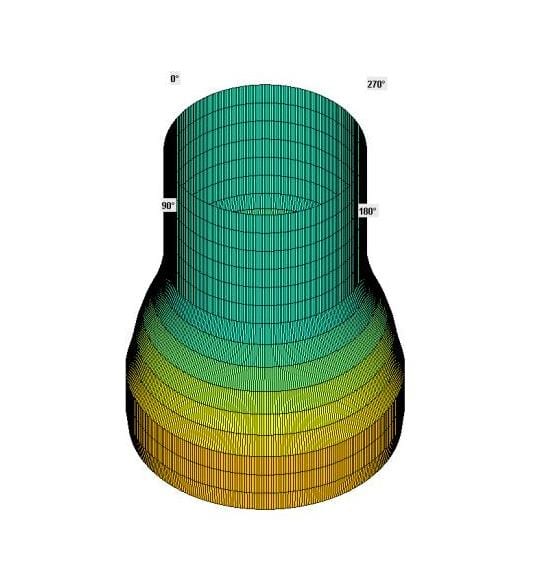 The shape data for the cylindrical deviations will be converted for every single cylinder of the engine using the form honing control. This dynamic process interaction between the feeding system, shape and the form honing tooling creates an optimal result.
Form honing professional has been implemented by customers for small production batch scenarios. The process produces cylinder deviations and surface finish profiles with high reproducibility and economical processing times. The process delivers free shapes and surface profiles with high reproducibility to conditions that still conform to cycle times.
The advantages of form honing have been recognized by engine manufacturers and have been implemented in numerous production lines on Gehring honing machines worldwide. Further series applications are in preparation.
About Gehring
For more than 90 years, Gehring has been the leader in the domain of honing technology, supplying cutting-edge surface finish technology solutions for internal combustion engines, gears and numerous other industrial applications. As a global technology leader, the company is represented internationally in key markets in the automotive and supplier industries, hydraulics and pneumatics, as well as aerospace sector.
The Gehring product portfolio ranges from individual honing stones to honing tools as well as gauging and automation solutions right up to integrated honing systems. Digital applications, services and innovative technologies in the areas of honing, laser structuring, roughening and coating complete the portfolio.
With standalone made-to-measure solutions for stator prototype development and small-scale series production, as well as fully automated new system solutions for electric motor production lines, copperING‘s product portfolio complements that of its new partner Gehring. The Gehring group therefore offers the full gamut of technologies for vehicle drives – from conventional solutions to hybrid technologies and even integral electrification.
The Gehring Group with approx. 800 employees, is headquartered in Ostfildern, Germany, and has additional locations in Naumburg and Wernigerode, Germany, as well as in the USA, China, India, Italy, UK, France, Brazil and Mexico.
For additional information and image material:
Jaqueline Fette (Director of Marketing)
Tel: +1 248 427-3943
Cell: +1 248 954 8383
E-Mail: jaqueline.fette@gehring-group.com
Gehring L.P.
24800 Drake Road
Farmington Hills, Michigan 48335
www.gehring-group.com
By Gerhard Flores, Manager of Technology Development and Intellectual Property
Gehring, Farmington Hills, Michigan
Note to editor: Information in this article was derived from the presentation given by Gerhard Flores at AGMA’s Fall Technical Meeting between September 24th and 26th in Chicago.
Gerhard Flores discusses the need for flat and curved surfaces with the functionality of high static friction for force-fitted nonslip power transmissions. This need is especially true for con rod and cam structuring for high torque resistance or front face connections of sprockets, gears or cam shaft adjustments. He details that expensive solutions like diamond layers, coatings or form fitting design are being substituted. Instead, innovative manufacturing is now performed by a modified laser process with defined exposed micro structures. The prerequisite for high friction is exposed micro melting burrs of smaller micrometer height with martensitic material structures. As a result, high static friction surfaces can be produced economically with repeatability of small tolerances in high-volume productions.
 Production of surfaces that generate static frictional connections with the counterpart are increasingly realized with a modified laser beam. The contact surfaces actuated by adherence are laid out with topographies that assure the functioning of work pieces and they can be produced in a cost-efficient way. The requirements of the connections include loads by torques and shearing forces. The system is kept is kept in a state of adhesive friction during the different operational conditions and does not allow any relative movement of the contact areas.
The principal feature of the adhesive system was revealed in a stress test. In it, hardened and structured contact surfaces are loaded against non-structured and unhardened ones with an axial force of 80 kN over 60 seconds for a twist angle of 4 degrees. The course of torque was indicated as target value. The contact areas (di= 15 m, da= 30 mm) were dry and free of grease. At the junction of adhesive and sliding friction, there is a maximum of adhesive value.
Using the adhesive friction bench or the functional aggregate, the effects of structure can be evaluated. Every structure that increases adhesive friction is characterized by a raised profile contour that has influence on the counter body. Next, manifold micro form profiles are produced to absorb shearing forces. Furthermore, the micro form profiles result in a frictional connection with high adhesive friction value. Due to the thermal effect of the laser beam, hardness is generated due to the short heating time.
There are significant differences in the laser structured adhesive friction surfaces of cams, connecting rods, front face connections and pre-treated substrate surfaces. Cam topographies can be raised with low profile elevations and without deepening. Material melts evenly. The structure lines of connecting rods are equidistant superposed. Both cam shafts and connecting rods can absorb torque of shaft hub joints. Between the structures of front face connections, there are often deepenings caused by material transfer. Lastly, pre-treated substrate surfaces display a squamous structure with micro recesses and are suitable to join layer materials to substrates.
Laser structuring of adhesive friction surfaces in rigid friction type connections can substitute positive locking design connections or other expensive friction type connections like diamond interlayers. The achievable adhesive value depends on the depth of the height, the profile shape of the laser structured roughness profile, the arrangement of the structure density, the martensitic properties of lasered materials, the normal force and whether the lubricant is embedded in the contact surfaces or not.
Different connections with torsional strength have different cylindrical contact surfaces. A shrinking connection with the laser structured inner surface of the cam and the shaft, enables the cost effective built cam shaft in serial production. In the case of the clamping connection shaft and the hub, the laser structured contact surfaces are engaged by clamping. This replaces the costly alternative of positive connections. In this way, pin or fitting connections can be replaced by friction type contact surfaces with high adhesive friction generated by the laser structured process.
Another category is the frictional connections of plain functional surfaces for the transmission of shearing forces of torques. The laser structured front surface, often designed with an alignment element replaces cost-intensive solutions like form-locked joint coupling with frontal tooling or inserted diamond or SiC interlayers as slices for the increase of the friction value. Applications related to the combustion engine like pinion, cam shaft adjuster, ball bearing or related to the chassis frame are becoming frequently demanded alternatives to the expensive solutions with slices and interlayers.
Laser structuring of the connecting rods is realized by means of the crank pin, which joins the connecting rod and the crankshaft. The design of the bearing consists of the rod eye, the bearing shell and the crank pin of the crankshaft. There is a rotational relative movement between the crank pin and the inner side of the bearing shell. The joint is laid out as a sliding bearing and works with low friction. However, there is no movement allowed between the outer side of the bearing shell and the connecting rod bore. Here, a sufficient high adhesion is required to absorb the frictions within the sliding bearing. Next, a frictional connection is necessary to deliver the suitable torque strength by means of the elevated topography of the connecting rod and the resulting adhesion.
For the process of laser structuring, a solid body laser with scanning optics is used. The two beam sources are arranged above the connecting rod eye laterally, the connecting rod bore. The beam sources work simultaneously and structure each of the two areas with the connecting rod bore. In each unit, the pulsed beam is guided by the galvanometer scanners with two galvanometer mirrors each. There is no mechanically actuated displacement or positioning of the beam and the focal movement is carried out quickly, line by line, with the highest precision and simultaneously by the movable optics of the integrated scanning heads.
The laser structuring of cams takes place after the shaft and cams are machined as single parts and are assembled by thermal friction type connected processes. In order to achieve sufficient torque strength of the cams, their bores are structured for enhanced adhesion.
Friction type connections are applied in several sectors of mechanical engineering and vehicle design for the transmission of shearing forces and torque. Frontal face connections with plain contact surfaces are laser structured in serial production. Cam shaft adjuster, chain pinions or gears are the focus of the central valve of Schaeffler with the cam shaft in serial production. This valuable technology reduces carbon dioxide emissions. By laser structuring of the main bearing, a high torsion strength of the bearing shell can be realized by the roughly structured areas of a cylindrical type connection as well as heat transfer by the smooth unstructured areas.
In conclusion, the advantage of laser structuring with integrated scanning is that the structuring segments on curved and plain surfaces can be freely dimensioned and positioned. In addition, the structure data and the tolerances of the different surface values can be adjusted by the beam parameter. The structuring process is completely automatable and can be integrated in a production line. Laser structuring allows an increase of static friction up to 5 times. Compared with diamond interlayers, the costs and number of parts is significantly lower.
For more information, please contact:
Jacqueline Fette
Marketing Manager
Gehring
24800 Drake Road
Farmington Hills, Michigan, 48335
Cell: +1 248 954 8383
Email: Jacqueline.fette@gehring-group.com
New technologies in honing, coatings, coolants, 3D measurement and digital factory solutions were presented by panel of industry experts; attracted 80 attendees
June 7, 2017 – Gehring held its 2017 Honing Conference and Workshops event on May 10-11, 2017 at the Inn of St. John’s in Plymouth, Michigan. The conference and workshops brought together experts from the global industry to discuss and propose solutions to advanced manufacturing challenges in surface finish technology applications. A total of 80 attendees, most from the automotive primes and Tier One suppliers, were treated to two days of learning, networking and fun.
 President of Gehring in the USA, Roger Cope, gave the opening remarks to kick off the event. He noted this was the 91-year anniversary of Gehring in Germany and that the company has had a manufacturing footprint in the USA for 41 years. An R&D facility in Livonia, Michigan was established several years ago to meet the demand for specialized honing process development, consulting and the rapid rise in demand for Gehring contract and prototype honing services. He further mentioned that Gehring has diversified its market focus in the last several years to include the defense sector and, in that arena, Livonia serves as an ITAR-compliant facility. The “One Gehring” theme codifies the global focus of the company, as it seeks to serve a global customer base, Cope said.
 Dr. Wolfram Lohse, CTO of the Gehring Group then took the floor and observed, “Part of our new business mission and focus globally is our desire to enhance customer and industry knowledge through the Gehring Academy for honing education, training, consulting and support in helping manufacturers implement and use our advanced honing technologies to their advantage, specifically to meet impending CAFE emissions regulations. We seek a partnership focus with key clients while retaining the highest level of integrity in handling confidential projects.” He discussed the drive to sustainability – another Gehring focus for the future. Partnerships with other key market specialists at this event, such as Oerlikon Metco AG, Nanofocus and Siemens, have been developed to produce a comprehensive resource for the market, with multiple sources of expertise relevant to surface finish technology.
Cope concluded his remarks by noting that Gehring is now a “one-stop shop” for all elements of the honing process – machines, tools, gauging, automation, rework, abrasives, R&D – with global support for global production platforms.
Gehring’s Director of R&D, Michael Schaefer, commented, “Gehring was honored to host this first unique conference, dedicated to Advanced Honing and Surface Finish technology, in the USA and to provide a high level technical and networking platform for professionals in this field with the leading manufacturers in the automotive and other industry sectors.”
During the conference, these presentations and workshops were conducted by industry experts:
-Gehring L.P. and Gehring Technologies GmbH, Michael Schaefer and Dr. Wolfram Lohse, “Advanced Honing Technologies Presentations”
-Oerlikon Metco AG, Wohlen, Dr. Peter Ernst, “Surface Enhancement with Thermal Spray Coatings”
-NanoFocus, Dr. Christian M. Wichern, “3D Surface Measurement of Cylinder Bore and Liners – Advantages and Challenges”
-Quaker Chemical, Frank A. Robinson Jr., “Chemistry and Functions of Honing and Coolant Applications”
-Gehring Technologies GmbH, Marcell Wardin, “Form Honing Cylinder Bores – from Development to Mass Production”
-Gehring Technologies GmbH, Dr. Wolfram Lohse, “Digital Solutions at Gehring”
-Siemens Digital Factory, Dr. Stephan Ihmels, “Mindsphere Application in Large Scale Automotive Production Scenarios”
80 process and manufacturing engineering personnel responsible for surface finishing in automotive, hydraulics, aerospace & defense part applications, including plant managers, production managers and R&D specialists attended this Gehring conference.
The technical program was supplemented by networking events such as the pre-conference “Infinity “chartered dinner cruise with entertainment on the Detroit River and post conference golf, all of which were enjoyed by the attendees.
For more information on this event, please contact:
Rita Conroy-Martin
Director of Marketing
GEHRING L.P.
24800 Drake Road
Farmington Hill, MI 48335
734-926-7538
rconroy@gehringlp.com
www.gehring.de/en
Gehring showcases their latest modular honing machines of the Lifehone and Powertrainhone series, complete portfolio and latest technologies at the IMTS!
FARMINGTON HILLS, MI – At IMTS 2014, Gehring will feature its new line of modular honing machines for precision metal components. Several machines from its new modular standard product families will be on display. These modular standard machines offer a systematic approach that is advantageous in establishing a highly efficient manufacturing process.
Integrating the technologies of the Gehring Group into these new modular product standards, the lifehone and powertrainhone will make their debut at the McCormick Center.
Small bore diameters often place different demands on the production technology than large ones. Due to customer requests and feedback from the market, we are showcasing our new lifehone machine with market proven components in a modular design. This new machine with inner column construction combines modern design with optimized accessibility. The rotary table is placed around the inner column so we can guarantee a quick access to the process stations, a good overview and a quick and easy changeover.
Alternatively equipped with a six or eight sided inner column you can fix up to 7 honing spindles. With this we can assure short cycle times and multistep processes. Pre and post gauging stations are fixed on the opposite side to optimize the interior space the best way possible. The compact design is resulting low space requirement in your facility. The Gehring Operator Panel can be led around the machine so that it is easily visible from any location, thus ensuring optimum flexibility and ease of use.

Gehring lifehone
All of our lifehone machines are characterized by ease of use and high performance. The lifehone can be constructed as a multi-spindle transfer solution for mass production, or as a single-spindle design for small production batches as well. You will find the right solution for your requirements and process conditions in our portfolio.
The powertrainhone is also part of a new machine generation with a unique modular concept. The innovative modular design system is comprised of standardized functional components which can be combined with tailor-made honing centers. This groundbreaking configuration enables new freedom and flexibility in production compared to modern hone systems with a conventional layout.
Gehring will also present its entire portfolio of honing technologies and services, from position and form honing, laser structuring to contract honing, displays of our tooling and abrasives, as well as a technical presentation titled “Honing of Thermal Coated Cylinder Bores” scheduled for Tuesday September 9, 2014 at 11.00am -11.55am by Mr. Gerhard Flores at the IMTS technical conference.
Gehring Honing Technologies invites manufacturers to visit them at booth N-6740 to meet with technology experts to discuss production honing solutions for the automotive and commercial vehicle, aerospace & defense, oilfield, job shop and other metal working industries. For more information on the Gehring product line and portfolio of honing solutions, please visit our website www.gehring.de.
Contact for press and publishers:
Rita Conroy-Martin
Gehring L.P.
24800 Drake Road
Farmington Hills, MI 48335
USA
Tel +1 (734) 395 2514
Cell +1 734 926 7538
Fax+1 (248) 478 9787
E: rconroy@gehringlp.com
by Gerhard Flores, Andreas Wiens, Oliver Stammen
Download the PDF HERE.
Summary
The possibility of position correction with high precision and material removal of up to 0.350 mm in 18 s puts the single-machine honing of transmission gears and other components firmly in the forefront of current automotive manufacturing technology. Despite very high cutting performance, the low machining forces and temperatures enable the lowest marginal zone variances and high residual compressive strength. The surface roughness with a high material content in low cutting depth and the hone angle structure have a positive tribological effect on the sliding function of the gear.
An additional innovative manufacturing strategy is the use of machines for combination machining. This fact is especially advantageous in the machining of planetary gears. Here, the process of flat finishing, ID grinding and honing are systematically combined in a single machine, as detailed in this presentation.
Introduction
The honing of gears, by definition, facilitates ease of operation, low noise and smoother performance in a transmission. Honing also contributes to reduced friction in the powertrain. Both the intense cutting (roughing process) as well as the functionally fine finishing of transmission gears can be performed in one setup, on one machine. Honing in mass production is a well-established process, owing to the intelligent machine layout and other combinations with defined cutting geometries. It should be technologically and economically considered as a serious production method. Furthermore, the combined process of flat surfacing and honing on one machine is a further recent innovation for the finish machining of planetary gears in mass production.
The design of components for modern vehicle transmissions such as manual, automatic or dual clutch styles seeks to reduce friction, thereby increasing gear efficiency in addition to function. Therefore, for the gear bores of various active transmission components and planetary gears, there is the requirement for low-friction and wear-resistant contact topographies. Also, there is the desire for economical finish machining of the bore in one process, whenever possible.
The finish machining of transmission components in mass production is currently being done using rough honing and finish honing. In one process, consisting of two steps on one machine, the functionally accurate shape and position tolerances, as well as the desired surface structure, can be achieved. Therefore, secondary hard turning and grinding processes are seldom required as finish processes in mass production, neither individually nor as combined processes in a work cell.
The diverse quality characteristics require an adjustment to individual process components of honing. The manufacturing quality of the conventional hone process is defined by the terms “dimensional tolerance” and “surface finish.” Furthermore, for the function of gear wheels, the quality terms “axial run-out” and respectively, “perpendicularity” and “radial run-out” (out of round) are relevant. If one also wants to use honing for the finishing of gear wheels, the process of these broadened quality terms is modified accordingly.
Function and Quality
The bore in a transmission component functions as a rotary and translational slideway. The tolerances are selected accordingly. The honed topography with high material mass benefits the frictional behavior and homogenizes the application of force. The honed surface profile with a large topographical contact surface enables a stabilization of the lubricating film, when mixed friction occurs. The loaded contact surfaces have a high adhesion for the gear oil, which prevents a breakdown of the lubricating film on the contact surfaces. This acts to reduce friction and minimize wear in the switched condition with high system pressure on the contact surfaces as well as the unloaded rotating idler. Also, the hone angles contribute to the even distribution of the lubricating oil in the lengthwise and circumferential direction of the bore.
In order to avoid local high surface pressures, there are also tight shape and position tolerances of the required macro-geometrical conditions for equal lubrication gap widths. The tight geometrical tolerances (axial run-out) and radial run-out have a positive effect on the smooth operation of the gear wheel sets. This is the purpose of the statistical tolerance limits. At a machine capacity of cmk 1.33, for example, the straightness is reduced from 3 µm to about 2.1 µm, despite very different wall thicknesses.
Honing involves the boring of gear wheels (such as planetary gears, transmission gears, switching sleeves, layshaft gears, bevel gears) of various shape, dimension, material and hardness. Honing of transmission gears goes beyond the previous quality terms. The following tolerances can be defined (Tab. 1):

Tab. 1: Quality characteristics for honing gears
In addition to the geometric tolerances, highly stressed components are increasingly evaluated according to the marginal zone of the functional surface. The mechanical and thermal stress of the material due to the machining forces during the final machining steps contributes to the microstructure in the area near the surface. Here, there are significant differences between the process used and the finishing operation. The honing process is one operation with comparatively low machining forces and temperatures. The conditions for developing a lasting, highly durable marginal zone are therefore especially advantageous with honing. Therefore, hardened parts are also the subject of material testing in terms of compressive stresses that positively influence the fatigue strength of highly stressed bore surfaces [1].
Honing Control Wheels – Machining Principle
An important feature of honing is the alignment of the tool axis and bore axis. In the conventional layout of tool and part, the expansion of the tool results in an equiaxial alignment. The tool-part system has designated degrees of motion freedom which enables the centering and tipping up to identical axis position. An improvement in dimension, shape and surface quality is achievable with this mechanical system.
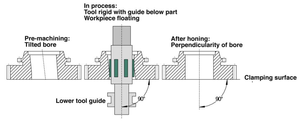
Dia. 1: Machining principle for position correction of gear wheel bores in gear wheels
If the position of the bore needs to be corrected, that is, the perpendicularity of the bore axis to the front face or the axial runout of the front face to the bore axis, the angular degree of freedom (tilting) must be replaced by a rigid perpendicular positioning of the tool axis and clamping surface [2]. The reference surface for honing is the machined front face, which is supported on the clamping level (Dia. 1). Centering on an inaccurate gear tip circle diameter is not necessary.
As a result, the center of the gear wheel bore can align itself to the tool via the floating part holder. Due to this condition, the radial run-out (bore to gear teeth) remains unchanged. The deviation of the angle position of the bore axis to the tool axis is corrected in the subsequent material removal. Next, the tool machines the raised areas of the lateral surface. With the additional clamping, the entire bore is machined and a new bore axis is established.
Honing Transmission Components – Machining Concept
The common principle among the various possibilities for gear wheel machining is the moveable part holder and the rigid tool holder. Also, the conventional honing process with adjustable honing stones has been carried through. For honing such components, vertical rotary indexing machines with the single part holder in floating fixtures are used (Tab. 2).
The preparation consists, as a rule, of boring and hardening, so that they must be machined in two honing operations. The tools are exclusively loaded with CBN-abrasives. Furthermore, fully automated production honing machines are equipped with various standard components such as gage stations, handling systems, force-controlled electromechanical feed devices (EMZ-F) and electromechanical ballscrew stroke drives.
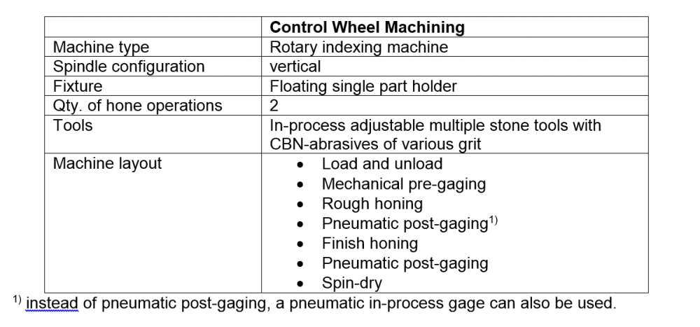
Tab. 2: Layout of honing machines for machining components
Honing Transmission Components – Requirements and Process Considerations
Because honing of hardened gear wheels has undergone major development in the past few years, this illustration is presented simply as an example. The hardened gear wheels are mainly machined on fully automatic, multiple spindle, rotary indexing honing machines. The machining concept for individual machining consists of conventional multiple stone tools. The attachments are designed to be interchangeable for various gear wheels. Honing a gear wheel bore is defined by the following quality terms and tolerances (Tab. 3):

Tab. 3: Required machining quality on a hardened gear wheel
The high stock removal during rough honing with a honing allowance of up to 0.350 mm is the prerequisite for the successful implementation of the honing process in the mass production of gear wheels. This is how honing maintains its competitiveness compared to hard turning. The smoothing of the surface end quality takes place in the 2nd machining station only by changing the cutting material and adjusting the process parameter. The radial run-out achieved in pre-machining should remain unchanged.
The layout of a machine for machining gear wheels shows the stations named in Table 2. After the load and unload station, the mechanical pre-gaging is performed. Here, the minimum dimension of the bore is checked, in order to prevent a collision with the tool. Rough honing works with robust parameters, especially with high cutting speed of about 150 m/min and large removal rates of about 20-30 µm/s in diameter. The subsequent finish honing operation completely removes the rough profile of the rough honing operation and leaves behind the functional component quality (Dia. 2). Pneumatic post-gaging is the final quality assurance; spinning the gear minimizes the spreading of the honing oil.
Dia. 2: Machining stations for honing gear wheels
The machining parameters are summarized in the following table (Tab. 4).
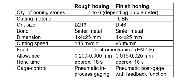
Tab. 4: Machining parameters for honing gear wheel bores
The high removal rate is primarily determined by the high delivery rate and high cutting speed. With increasing rpm, a rise in material removal is clearly noticeable (Dia. 3). The mathematical removal characteristic is determined by the feedrate, i.e., by the diametric preset diametrical honing stone feed per unit of time. The difference between calculated and measured stock removal results from feed losses caused by deflecting the components in the complete feeding system. The increasing deviation from about 1500 rpm is explained by an increase in coolant flow at increased rpm. The influence of the stroke speed in the area examined in not significant. Because of the material properties and the high cutting capacity, the rough honing operation produces less fine-grained hone sludge. Instead, fine, long continuous chips in the form of a steel wool ball result.
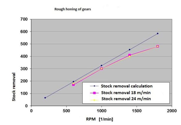
Dia. 3: Correlation of rpm and stock removal (control wheel diameter 35 x 26 mm, forged steel, 680 HV30, hone time 18 s, L600 honing machine)
The function of CBN-abrasives of a middle concentration (stock removal 0.300 mm in 18 s) is decisive for the entire process. The use of low viscosity honing oil ( = 4.6 mm²/s) has a positive effect on the cutting behavior and, thereby, on the consistent manufacturing quality and tool life. In addition to the constructive design of the hone tools, the condition of the abrasives is of vital importance. They are composed of a metallic binder, fused with the proper concentration of CBN-abrasive crystals (Dia. 4). Apart from the selection of binder and grain material, the sinter parameters in the manufacturing process of honing abrasives determine the quality. The hone tools are rigidly connected to the spindle. Below the part, the tool body is formed as a carbide reinforced guide shaft. The tools, depending on design feasibility, have as many abrasives as possible. This improves the machining accuracy with regard to dimensional stability and increases cutting performance and tool life.
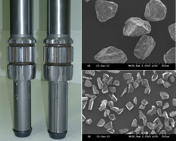
Dia. 4: Hone tools with lower guides and CBN-abrasive crystals (B213 / B46)
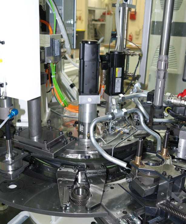
The individual processing with conventional abrasive tools is the most economical variation of gear honing. The stationary fixtures are arranged under the two hone spindles. With the rotary index movement, the gears are loaded into the fixture. The fixture consists of the floating part holder and the zero-clearance hold-down device (Dia. 5). The part is situated on one of the flat sides of a moveable pallet. The hydrostatic friction bearing of these pallets enables effortless but not undamped movement on the flat. A torque recorder in the gear teeth has been proven effective. This occurs by means of the insertion of the gear into an integrated switch sliding sleeve or by applying a safety catch. The zero-clearance hold-down to accept the upper facing axial force helps with the deformation-free fixation of the gear. The lower guide stabilizes the tool axis to the clamping level at a right angle.
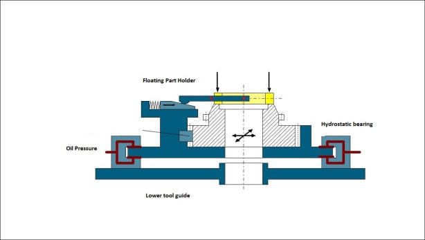
Dia. 5: Floating uptake with zero clearance hold-down
The described process design can reliably achieve the required tolerances. The roughness and the axial run-out are not statistically evaluated here. With the finish hone stones (B46), the Rz-value amounts to about 1.5 – 2.5 µm and the axial run-out precision of 15 to 25 µm only meets about 40% to 50% of the tolerance. The cycle time achieved is 20 s with an allowance of 0.300 mm in the 1st operation (determined by cycle time). The quality parameters of diameter, roundness and parallelism are also calculated to meet tolerances and satisfy the statistical tolerance limits.
Measuring the compressive stress with the help of x-ray diffraction shows the condition of the material structure in the area of the marginal zone of the honed bore surface. The compressive and tensile stresses in the sub-surface are depicted. The stress in the area of the functional surface is substantially influenced by the hardening process and the stress of the finishing operation. The penetrating x-rays are reflected in the relaxed marginal zone according to the particular grid pattern of a material at a constant angle. Tensile or compressive stresses, however, imply deviations in the grid pattern from the normal value for the relaxed state, caused by the machining forces of the finish operation. They are verified by changing the reflection angle. In terms of fatigue strength, the highest possible compressive stress (-) is always advantageous [3].
The available measurements (Dia. 6) were taken with a Stresstech XSTRESS 3000 instrument. The values were measured axially and tangentially. The hone angle of about 20° causes an uneven distribution of the compressive stresses in both directions on the honed surface. With increasing material depths, that is, with diminishing influence of the machining forces, a broad homogenization of the clamping is measurable. The achieved results indicate the advantage of the honing process. They clearly exceed the values of competitive processes such as hard turning [2] or grinding.
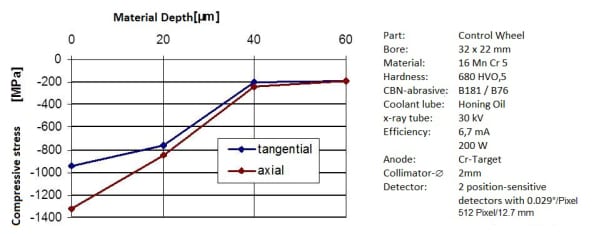
Dia. 6: Progression of compressive stress with increasing material depth
Honing planetary gears in combination machining
The combination machine with the processes of flat finishing, grinding and honing offer a new possibility for machining planetary gears, as shown here. This rotary indexing machine completes the processes on the part, one after another in one clamping. This allows various machining geometries, such as one bore and one face surface to be machined, each with tight tolerances relative to the other. The compact machine workspace essentially consists of a circular rotary table, on which the rotary driven units are constructed and the central column, where the machining units are assembled to the upright surfaces. The result is a self-sufficient machine with a small footprint and short transport route in the indexing of the part. The circular rotary tables make the machining units easily accessible for maintenance work and tool changes.
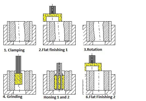
Dia. 7: Process steps for combination machining
Dia. 7 depicts the process steps for such combination machining. The part is only pre-machined on the front and in the bore. The gear wheel is located in the fixture with an unfinished side up and is clamped radially on the gear teeth. The tip diameter or the involute teeth are the geometric identifying elements for the position of the part. The upper front is machined by flat finishing 1. Then, the part is turned, so that the previously finish-machined end surface fits in the fixture as the locating surface. In the subsequent grinding operation, the bore is ID ground centric to the gear teeth. With this, the desired radial run-out tolerance is achieved.
This enables the subsequent station to work with a tightly clamped hone tool because the alignment is made to the unchanged clamping fixture and guarantees the centric ground bore. Therefore, a new bore axis will not be partially processed. The hone process consists of a rough hone and finish hone operation. Between the two hone operations is a gage station, in which a plug gage records the rough hone diameter using the principle of pneumatic length measurement. After finish honing, the flat finishing 2 takes place. Here, the second end face is machined parallel to the first end face.
Diagram 8 shows the individual machining stations, with the flat finish machining directly after the load and unload station in the left-hand photo. In the right-hand photo, the grinding spindle directly before plunging in the part is depicted. The middle photo shows the honing stations arranged after grinding, as well as the gage station for measuring the diameter after honing. All stations together work the rotary driven part. This is especially unusual in a hone process, but allows a significantly simplified spindle set-up. The hone tool only performs a feeding movement and a stroke movement.
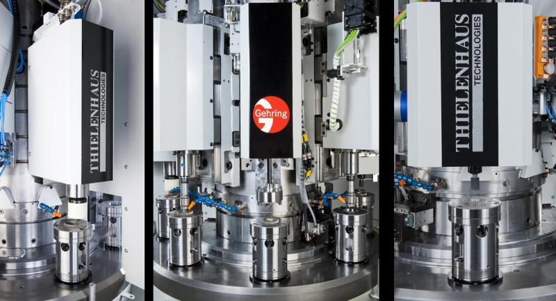
Dia. 8: Machining stations for machining planetary gears
The machine concept is designed such that other process sequences are configurable. There is also the opportunity to integrate modified modular units such as deburring, wheel dressers, belt finishing or reaming. The concept of combined machining is especially useful in the manufacturing of planetary gears. Previously, the manufacturing processes for flat finishing, ID grinding and honing required different machines.
The consolidation of the processes into one machine allows high capital investment savings, increased productivity and reduced operational footprint. (Dia. 9). For planetary gears, cycle times of 7 s with material removal in the bore of ≤ 0.15 mm are achieved.
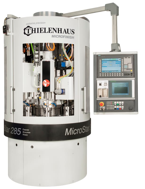
Dia. 9: Machine for combination machining of gears
—
Download the PDF HERE.
For more information on this article, please contact:
Gehring L.P.
24800 Drake Road
Farmington Hills, MI 48335
Phone: 248-427-3901
www.gehring.de
rconroy@gehringlp.com
Rita Conroy-Martin, Inside Sales & Marketing Support
![]() |
| ![]() |
|  |
| 
Info on Authors
Dipl.-Ing. (FH) Gerhard Flores is Manager of Process Development at Gehring Technologies GmbH in Ostfildern, Germany and a lecturer at the technical university in Esslingen, Germany. His associate, Dr.-Ing. Andreas Wiens, is Team Leader of Process Development for Gehring Technologies GmbH in Ostfildern, Germany.
Gehring Technologies GmbH
Gehringstr.28
73760 Ostfildern
Germany
gerhard.flores@Gehring.de
www.gehring.de
Dipl.-Ing. Oliver Stammen is Sales Manager for Thielenhaus Technologies GmbH in Wuppertal, Germany.
Thielenhaus Technologies GmbH
Schwesterstraße 50
42218 Wuppertal
Germany
stammen@thielenhaus.com
www.thielenhaus.com
Technical References
[1] U. Klink, G. Flores: “Honkonzept mit cBN verbessert die Laufruhe und Qualität von Zahnrädern.” IDR Industrie Diamanten Rundschau 34 (2000) Nr. 1 S. 12 – 19
[2] U. Klink: “Wirtschaftliches Honen von Getrieberadbohrungen.” Werkstatt und Betrieb, 116. Jahrgang 1983, Heft 5, S. 283-286
[3] B.A. Shaw, J.T. Evans, A.S. Wojtas and L. Suominen: “Grinding Process Control Using the Magnetic Barkhausen Noise Method.” Third International Workshop on Electromagnetic Non-Destructive Evaluation. Reggio Calabria, Italy, 14. – 16. September 1997. IOS Press in the Series ‘Studies in Applied Electromagnetics and Mechanics’.
Continue reading
Bernard & Company is proud to announce recent client acquisitions including Suhner Automation, Gehring Technologies GmbH, Chemcoaters, Gray Machinery and S & G Press & Machinery Sales, for which they will be providing full advertising, PR, social media, trade-show and online promotional activity.
![]()
Since 1926, Gehring L.P has been a globally operating machine tool company specializing in high performance honing technology.
Website | ThomasNet Profile | ![]() |
| ![]() |
| ![]() | 24800 Drake Rd. Farmington Hills, MI 48335 | (248) 427-3901
| 24800 Drake Rd. Farmington Hills, MI 48335 | (248) 427-3901

Founded in 2001, Chemcoaters‘ continuous, coil processing line is designed specifically for the most economical application of environmentally friendly waterborne coating sys-tems.
Website | ![]() |
| ![]() |
| ![]() |
| ![]() |
| ![]() | 700 Chase St. Gary, Indiana 46404 | (219) 977-1929
| 700 Chase St. Gary, Indiana 46404 | (219) 977-1929
![]()
Established in 1966, Gray Machinery Company has over 40 years of experience buying and selling pre-owned machinery.
Website | ![]() | 77 E Palatine Rd. Prospect Heights, IL 60070-1811 | (800) 292-1493
| 77 E Palatine Rd. Prospect Heights, IL 60070-1811 | (800) 292-1493
![]()
Founded in 2000, S & G Press & Machinery Sales operates worldwide, buying and selling used stamping and manufacturing equipment; specializing in metal stamping presses, feed lines and various types of automation, fabricating and tool room equipment.
Website | ![]() |
| ![]() | 16660 East 13 Mile Rd. Roseville, MI 48066 | (586) 563-5000
| 16660 East 13 Mile Rd. Roseville, MI 48066 | (586) 563-5000
![]()
Since 1914, SUHNER Automation has been providing economical, low-cost manufacturing solutions and machining units for drilling, milling and tapping operations.
Website | ThomasNet Profile | ![]() | 43 Anderson Rd. Rome, GA 30161 | (706) 235-8046
| 43 Anderson Rd. Rome, GA 30161 | (706) 235-8046