
Contact us today:
(847) 934-4500
tdaro@bernardandcompany.com
Contact us today:
(847) 934-4500
tdaro@bernardandcompany.com

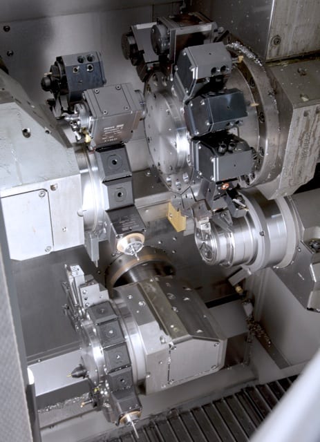
VA 700 T – Joining machine for the manufacture of composite camshafts. While one cam is heat shrinking, the next one is preheated. Equipping the heat shrinking machine with a number of preheating units allows for the optimal application of this technology to suit the task at hand.
The composite camshaft is still gaining ground in the marketplace. The main reason for this is the considerable weight reduction it brings, compared to its one-piece rival. The composite version is by now also widely used in the HGV sector. However, the main disadvantage of many current assembly processes is the high joining force applied, which creates unacceptable tolerances in positioning and alignment of the cams. By contrast, the patented heat shrink assembly process from EMAG offers a decisive advantage, as it ensures that “ready-to-fit” camshafts, gear shafts and other precision composite units can be produced without problems.
The advantages of the composite camshaft are well known: less expense, less weight, the possibility to use different materials for the various constituent components, greater flexibility in production and the ability to implement new cam geometries, such as negative radii, with ease. The necessary reduction in fuel consumption – and with it those of CO2 emissions – are easier to achieve with an increasing use of composite camshafts.

Also used for gear shafts, heat shrinking of the constituent components ensures a compact design and high functional density, as the gears are in direct contact with the shoulders.
Alternative processes for the joining of cam and shaft have one serious disadvantage: the two components cannot be joined with the necessary accuracy to avoid a subsequent finish grinding process. In many cases, the joining of cam to tube is carried out using a form-fit process like press-fitting, knurling and/or spline/serrated gearing. The joining forces required for these processes can deform the components and result in unacceptable tolerances in cam position and orientation.
The heat shrink assembly process from EMAG means precision joining
Thermal joining, i.e. the heat shrinking of cam onto tube, ensures that the required tolerances are achieved with a reaction force-free process. The know-how to tightly control the process parameters of “temperature” and “time” – and the mechanical design of the joining equipment – are of the utmost importance in this process.
An optimal combination of robot and special-concept gripping technology allows for fusion gaps of < 15 µm to be achieved safely. The concept’s great flexibility allows camshaft designers more freedom in their designs and ensures that the process can also be used for medium batch sizes, where frequent component type changes are the order of the day. The high degree of precision of the composite camshaft drastically reduces the need to subsequently grind the cams or – where precision cams are used – does away with the requirement completely. A further advantage of this process lies in the possibility of using different materials for the composite shaft. This includes forged cams, for instance in 100Cr6, or finish-ground cams, even dimensionally accurate sintered cams that do not require a downstream finish-grinding operation. Secondary components, such as bungs and endpieces, can – just like the actual shaft itself – be made of more advantageous materials.
All this allows the camshaft to be made to suit the requirements of the engine and to optimize it in terms of load bearing capacity and manufacturing costs.
And now one step further:
Where the camshaft needs to be ground after heat shrink assembly, the joining machine can be linked up to a grinder. This is particularly easy when using an EMAG grinding center of the VTC DS Series. With this setup, the joining machine robot transfers the assembled camshaft directly to the loading position on the grinding center. The advantages of this process from EMAG also apply to the machining of other components. When machining gear shafts, ground gears can be joined tightly on the shaft, without needing to account for the grinding wheel overrun at the design stage. It also minimizes the length of the shaft and makes the whole unit more compact.

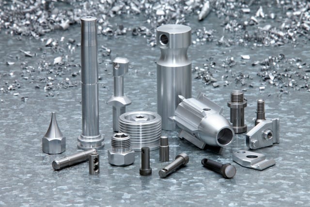
Ready-to-fit, complete, heat shrunk assembled camshaft. The high degree of precision of the composite camshaft drastically reduces the need to subsequently grind the cams or – where precision cams are used – does away with the requirement altogether.
Maximum flexibility
The EMAG process is characterized by only a very few machining components being in direct contact with the workpiece. It allows for the machines to be reset in the shortest possible time (typically less than 15 minutes).
Joining in seconds and achieving the highest possible quality
The heat shrink assembly process offered by EMAG combines flexibility with productivity, while freedom of design and choice of production technologies ensure a short cycle time. While one cam is heat shrinking, the next one is already being preheated. Equipping the heat shrinking machine with a number of preheating units allows for the optimal application of this technology to the task at hand. It is these advantages that may well be the reason why so many firmly established manufacturers of camshafts and other precision assemblies are showing such a great interest in the new process, are asking for machining tests, or are already applying the process under actual production conditions. In the ideal case, the customer will take advantage of the synergy provided by the EMAG Group and ask for a complete concept to be prepared that covers everything from pre-machining to heat shrinking and end machining.

Finished assembly of a motorcycle camshaft. An optimal combination of robot and special-concept gripping technology allows the pieces to join with a fusion gap of
The advantages of the heat shrink process:
The advantages of the composite camshaft:
For more information, please contact:
Kristal Kilgore
EMAG LLC
38800 Grand River Avenue
Farmington Hills, MI 48335
Tel: (248) 875-0313
Fax: (248) 477-7784
E-mail: kkilgore@emag.com
Web: www.emag.comEMAG LLC
38800 Grand River Avenue
Farmington Hills, MI 48335
Tel: (248) 875-0313
Fax: (248) 477-7784
E-mail: info@usa.emag.com
Web: www.emag.com
Attention: Peter Loetzner
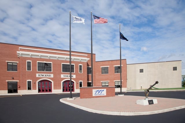
Continue readingWhen Task Force Tips, Inc. (TFT) decided to study the true costs of ultra-priced, high-speed machining, the company expected nominal gains on its machine-control investment; but when TFT began cutting the same precision parts in one-third of the time, it was, in the words of the company owner and president, Stewart McMillan, “a wake-up call.”
See the video on this story HERE.
 Breaking the price/cost perception barrier
Task Force Tips (TFT) is a manufacturer of highly engineered fire suppression tips, nozzles and other agent delivery equipment used by fire departments globally. For more than four decades, the company has always invested in premium machine tool brands associated with quality, performance and logically, higher price tags. Even so, it was the latter variable – the perceived barrier of price and cost – that prevented company owner and president, Stewart McMillan from ever considering more ultra-priced, high-speed machining options on the market.
“I hadn’t really looked at the economics when it came to an INDEX machine,” recalls McMillan. “And why? Because it always seemed like the INDEX brand was so prohibitively expensive. I never even thought its machines were within our league.”
That was prior to IMTS 2008, before TFT brought the company’s first INDEX machine into its 168,000 square foot facility in Valparaiso, Indiana, where TFT manufactures over 5,000 products across three shifts, seven days a week, all year around.

The Index C100’s “literal” coordinate system establishes actual reference points for programming the machine’s precise motion, rather than use arbitrary points in space.
“It was an INDEX C100 automatic production lathe, ultimately fitted with a Siemens 840D control package,” McMillan says. “We started making parts on it and our production times became typically 30%. I don’t mean a 30% reduction. I mean our run time for a part dropped to 30% of what it was before.”
As to why the company’s new machine made such an unprecedented productivity impact, McMillan points to both the high speed design of the machine and to the equally capable Siemens control package, which represented yet another paradigm shift for TFT.
Previous to the INDEX C100 purchase, TFT had scant experience with Siemens control packages. Much like the INDEX brand, Siemens five-axis controls were perceived as prohibitively sophisticated and just plain different. This lack of familiarity had been reason enough for TFT not to consider Siemens.
These were the company’s perceptions in 2008, before the INDEX C100 machine came into the plant, powered not by a Siemens control package, but by a more commonly accepted brand of CNC.
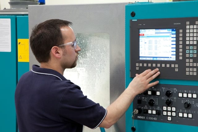 “We had all kinds of bugs in the control that came with the machine the first time,” McMillan recalls. “INDEX had a particular customer that had insisted on another more familiar brand of control, and so they were making the machine with that control. I don’t think that the other customer realized just how significant the Siemens control was to the machine. We didn’t recognize it either. A service representative commented to one of my employees that we really should have the Siemens control for what we were doing, that we were pushing the machine far beyond the capabilities of the original control.”
Upon learning that its new machine was underperforming for TFT, McMillan says INDEX swapped out the machine with an identical model, with one difference. This time, the INDEX C100 was powered by a Siemens motion control package, and TFT was able to set out in earnest to explore what price/cost lessons could be learned from its machine tool investment.
Zero to 5,000 RPM in one second
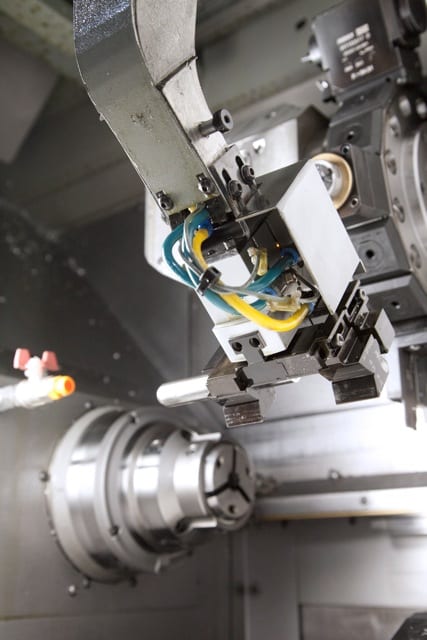
The INDEX C100 features automated remnant removal. The design has helped TFT increase revenues by eliminating the production delays caused by manual remnant stock removal cycles– typically not an option on lower priced machines.
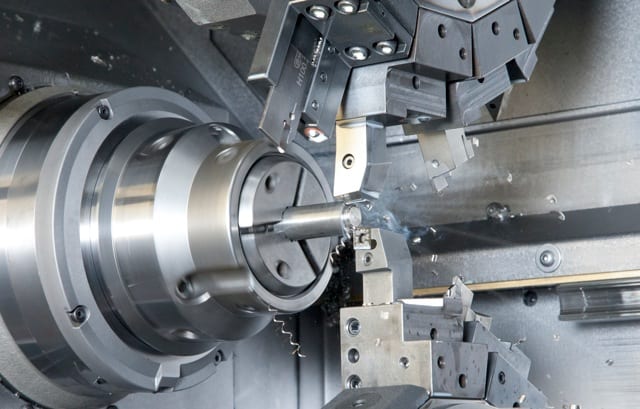
McMillan recalls that an immediate revelation was seeing the difference a few thousand RPMs can make. The company began to run jobs at 5,000 to 6,000 RPM, ramping up from zero to 5,000 RPM in less than one second and ramping down just as fast. Several economic lessons soon emerged from this capability, as the sustained speed of the machine maximized motion in new time/cost saving ways.
“We never realized before just how much time we were losing waiting on the spindle to stabilize at a new commanded speed,” McMillan reports. “The turret indexing was also extremely fast, with the multiple tools overlapping to cut at the same time with incredibly fast accelerations.”
The INDEX C100 also leverages speed in new ways, as TFT discovered. The company can run more than 1,000 parts without having to change an offset. In addition, an automated remnant removal feature enables the machine to run continuously, by rapidly reloading bar stock without operator interaction.
“On the rest of our machines, we need to pick the remnant out and load a new bar into it,” McMillan explains. “That step should take just a few minutes. But the way things work, a machine can sit idle for six minutes before somebody realizes it, and then it takes five minutes to reload, and all that lost time adds up.”
Another speed-related discovery was the integration of rapid traverse rates, which have always been less than rapid in the company’s experience “A lot of machines advertise rapid traverse rates at maximum speed, but the fact is, unless you’re traveling 10 or 12 inches, traverse speeds have never reached maximum for us.”
Taking motion accuracy literally
As to how the machine eliminates slower traversing and other cost related functions, McMillan says the design of the INDEX C100 is unlike the design of conventional and yes, lower-priced machine bed coordinate systems.
“The INDEX doesn’t use the same coordinate system as other machines. It uses a set of parallelogram bars, a very unique system for rigidity,” McMillan explains. “The machine has a picture frame mount for its turret. The turret is not leveraged off a set of ways like most turrets. It’s close to where it’s sliding, so there’s not a big length over diameter ratio in terms of the tools of the turret hanging out from its support structure. This gives the machine a lot of rigidity for turning, and you can accelerate the axes so fast that you really do achieve faster traverse rates. The window on this machine is just a blur of motion.”

The coordinate system of the INDEX C100 uses a set of parallelogram bars for uniquely rigid motion that is fully exploited by the Siemens SINUMERIK 840D.
TFT’s lead programmer, Nate Price, sees additional efficiency advantages made possible by the INDEX machine’s unique coordinate system, whereby measurements and motion can be programmed based on actual numerical reference points and not on arbitrary points in space.
“On the INDEX, every machine space coordinate, every offset, every measurement that’s used to define how the machine operates has a legitimate explanation of why it is what it is and to where it relates,” Price explains. “This makes it much easier to automate these measurements; whereas, in the past we would measure manually, because these were arbitrary points. On the INDEX, they are defined, literal points. We know exactly what they relate to, so we can define them automatically before the program ever gets to the machine, before the set-up ever starts.”
(Click here to see: Normal Lathe Coordinates and Index C100 Coordinates)
Advanced cost control
 With the Siemens 840D control package driving the INDEX C100, TFT would document yet more lessons in machine tool economics, including reduced setup times. The faster indexing speed of the turrets contributed to an 80% reduction in setup times compared to the setup times of TFT’s other premium machines.
According to Price, the Siemens 840D control interface brought a refined and intuitive approach to machine programming, setups and operation — an approach that was especially empowering to him as a programmer.
“I don’t know if anybody just doing set-ups would understand how much of a difference the Siemens control has made in the programming,” Price explains. “It has enabled me to more quickly and easily write the programs, write the post-processes, thus making the setup of special routines go much faster.”
In addition to easier programming and faster setups, Price says the machinists have found that the Siemens 840D enables them to more efficiently control and capitalize on the production potential of the INDEX machine.
“The control gives you ample shortcuts,” says Price. “There is a method of presenting messages to the operator that was not present in the other control. There is so much happening on the machine, it is really difficult to capture all that information on a single screen, but the control helps you keep track of what everything is doing. It’s really easy to get into more detail, without having to go through a lot of pages.”
As another example of CNC operational efficiency, Price points to the way the control manages error messages.
 “The machine wants to see several conditions exist before it will start a cycle,” Price explains. ”On the previous control, it was not real good at telling you that it was not in a condition to start a cycle. It wants the chucks closed. It wants the gantry in safe position. It wants the sub-spindle in a safe position. It wants to know where everything’s at and it presents a giant list for the operator to reference in order to start a cycle on the machine. But, when you press Cycle Start on the Siemens control, if those conditions aren’t met, the control will guide you through what needs to change to meet those conditions, so you can start your cycle.”
Another advantage brought about by the Siemens control was faster tool loading, made possible by faster and easier CNC programming.
“Tool loading was a big area of improvement,” Price says. “You essentially give the control a mini-program that tells it what tools you’re going to be putting in for this job that you’re setting up. The control will then present the stations on the turrets for you, tell you what tools to put in and what tools to take out. And it’s entirely guided. This has been a huge departure from what we traditionally had dealt with. It really accelerates set-up time.”
More profit per square foot
 McMillan and Price claim that the lessons derived from their machine-tool investment can be measured in broader and perhaps even more dramatic ways.
“I started to look at the numbers from a different perspective,” McMillan relates. “You have all these initial and ongoing costs to build a shop, to put in a floor, to put a roof over it, heat it, cool it, and all these costs can equate to so much per hour. Now you buy a machine that’s $600,000 versus a machine that’s $300,000 over 10 years. We run almost 24 hours a day, seven days a week, which helps our analysis. For us, it comes out to about an eight dollar per hour difference to buy the $600,000 machine. And for eight bucks more an hour, we’re getting triple the production out of that same square footage.”
Another way the company has measured its return on its investment in advanced machine-control manufacturing has been to witness the change in the people uplifted by the technology. Now, owner, programmer, machinists and others at TFT are enthusiastic about the possibilities of their more advanced, CNC-based manufacturing.
McMillan says that it will be such investments in machines and in people that will keep his company from selling itself short, having proven that with the right machine and the right motion control technology, anything is possible.
“We had a job that ran a couple of weeks ago,” McMillan recalls. “I received several e-mails before I even came to work that day. Different people were sending me e-mails that said in effect: Wait until you see what we’re doing with the INDEX today!”
See the video HERE!
For more information, contact:
Siemens Industry, Inc.
Motion Control Business — Machine Tools
390 Kent Avenue
Elk Grove Village, IL 60007
Tel: (847) 640-1595
Fax: (847) 437-0784
Web: www.usa.siemens.com/cnc
E-mail: SiemensMTBUMarCom.industry@siemens.com
Attention: John Meyer, Manger, Marketing Communications
Twitter: www.twitter.com/siemens_cnc_us
Facebook: www.facebook.com/SiemensCNC
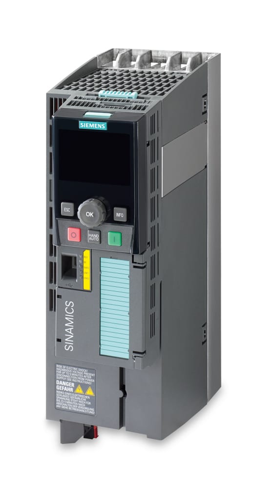 Siemens announced that its versatile Sinamics G120 drive system has been enhanced to include EtherNet/IP connectivity, thus providing maximum flexibility for industrial Ethernet communication while offering innovative concepts for those wanting a single network for the entire plant.
“In many instances, plant managers have the requirement for a single-plant network, particularly with large automotive, packaging, plastics, metals, food and beverage as well as material handling companies,” says Robert Soré, Siemens product manager, Sinamics G drives. “Our Sinamics G120 drive provides communications without limits to a specific network type.”
The Sinamics G120 drive platform supports, as standard, Profibus DP and Profinet to ensure seamless communications between every component involved in a typical automation solution, including HMI (operator control and visualization) and I/O. Additional higher-level functions, including Safety Integrated telegrams and synchronized mechanisms for even the highest-level control applications, are
also included.
Profinet can transmit operating and diagnostics data simultaneously to enterprise-level systems using standard IT mechanisms (TCP/IP) for an integrated factory environment. The new addition of an EtherNet/IP stack offers another option for Sinamics G120 users. Having the flexibility to communicate with the most common automation systems via Profinet or EtherNet/IP makes the Sinamics G120 drive system easily adaptable to the current Industrial Ethernet boom.
With a wide power range (0.50 – 350 hp), highly scalable solutions, including safety integrated functionality and convenient start-up with Siemens Starter software, the Sinamics G120 drive is a powerful solution for a variety of applications, including packaging, plastics molding and extrusion, textile, printing and paper machines, handling and assembly systems, rolling mills and test stands.
See the SINAMICS Drives video on YouTube here.
For more information about the Sinamics G120 drive platform, visit www.usa.siemens.com/sinamics-g120.
For specific product information and inquiries, call (800) 879-8079 ext. Marketing Communications or send an e-mail to: SiemensMTBUMarCom.industry@siemens.com.
Continue reading
Hennig custom enclosures and fuel tanks provided for three Cummins 2MW generators at Broken Arrow, Oklahoma project for Cummins Southern Plains LLC
![]() Machesney Park, Illinois – The City of Broken Arrow’s only existing water treatment plant, erected in 1966, could no longer satisfy the needs of the 35,000 homes and businesses, requiring the City to purchase water from other facilities and nearby Tulsa. In cooperation with the Oklahoma Department of Environmental Quality and the Oklahoma Water Resources Board, a new municipal water treatment plant on the shore of the Verdigris River will provide up to 20 MGD (plant rating at 20 degrees C) of water daily to the City of Broken Arrow, Oklahoma.
Machesney Park, Illinois – The City of Broken Arrow’s only existing water treatment plant, erected in 1966, could no longer satisfy the needs of the 35,000 homes and businesses, requiring the City to purchase water from other facilities and nearby Tulsa. In cooperation with the Oklahoma Department of Environmental Quality and the Oklahoma Water Resources Board, a new municipal water treatment plant on the shore of the Verdigris River will provide up to 20 MGD (plant rating at 20 degrees C) of water daily to the City of Broken Arrow, Oklahoma.
The project began in early 2012 with the bid for the standby power system awarded to Cummins Southern Plains LLC, Tulsa, for the parent company based in Arlington, Texas. The project will utilize three 2 MW generators powered by Tier II emission certified Cummins 16 cylinder QSK 60 series diesel engines.
Due to the environmental and acoustic specifications of the water treatment facility, special enclosures and fuel tanks for the generator sets were required. Cummins Southern Plains LLC sales representative Mike Teague asked Hennig Enclosure Systems (Machesney Park, Illinois) to provide a possible solution. As Mike explained, “Al Grabowski from Hennig had been in contact with Cummins Southern Plains. We gave him the opportunity to quote the project and were quite pleased with the results.”
Cummins Southern Plains LLC provided the performance characteristics of the generator sets to Hennig Enclosures Systems, who then provided submittal drawings of the enclosure packages in Solid Works CAD format for the customer to review. Each enclosure measured 40’ long x 10’ wide and nearly 14’ high to allow ample airflow and provide a 25 dba sound reduction. After the customer and contractor approved the drawings, Hennig Enclosure Systems began cutting and bending steel. “Hennig is a one-stop shop. We manufacture the entire enclosure and fuel tank in addition to mounting the genset and landing all the electrical connections for the customer,” Grabowski added.
The Hennig solution involved a topcoat finish of TGIC polyester powder coat paint for weather resistance and UV protection. Grabowski notes, “Hennig utilizes a durable powder coat finish along with stainless steel hardware on every enclosure we build to meet the broad range of environmental conditions across the United States. We want our enclosures to look as good in 20 years as they do the day they were installed.”
A few weeks after the generator sets arrived at Hennig, the enclosure and fuel tank packages were ready to ship. There were some logistics challenges on this project, as the facility site was in the midst of construction. Delivery was made down a temporary dirt road and the three 2 MW Cummins emergency power generators were set in place without a hitch at the new Broken Arrow Water Treatment facility site.
The Broken Arrow municipal water treatment facility is primarily funded by loans totaling $64.8 million, administered by the Oklahoma Department of Environmental Quality and the Oklahoma Water Resources Board. The facility is being constructed by Crossland Heavy Contractors of Columbus, Kansas. The first phase of the project is scheduled to be operational in July, 2013.
-0-
Hennig Enclosure Systems, a division of Hennig Inc., manufactures innovative enclosures and fuel tanks for standby/emergency/prime power/peak shaving generators and switchgear. Hennig enclosures are designed and built to provide environmental protection and meet today’s demanding acoustical requirements of power generation equipment. The company operates facilities in Machesney Park, IL. To learn more, visit www.hennig-enclosure-systems.com.
Hennig, Inc. designs and produces custom machine protection and chip/coolant management products for state-of-the-art machine tools. Hennig products are designed to protect against corrosion, debris and common workplace contaminants. Manufacturing facilities located in the USA, Germany, France, Brazil, India, Japan, Czech Republic, England and South Korea. Repair centers are located in Machesney Park, IL; Chandler, OK; Livonia, MI; Blue Ash, OH; Mexico City, Mexico; and Saltillo, Mexico. To learn more, visit www.hennigworldwide.com.
To learn more about Hennig products & services, visit www.hennigworldwide.com or call 1-888-HENNIG6 (436-6446).
Tim Waterman
Hennig Inc.
9900 N. Alpine Rd.
Machesney Park, IL 61115
(815) 316-5277
info@hennig.ame.com
www.hennigworldwide.com
Connect with Hennig online: ![]()
![]()
![]()
![]()
![]()
![]()
![]()
For more information on Cummins Southern Plains in this story, please contact:
Cummins Southern Plains LLC.
525 E. Skelly Drive
Tulsa, OK 74116
Phone: 918-234-3240
 No. 1027 is a 550ºF electric cabinet oven from Grieve, currently used for drying pellets in pans at the customer’s facility. Workspace dimensions on this oven measure 47” W x 30” D x 63” H. 30 KW are installed in Incoloy-sheathed tubular elements to heat the oven chamber, while a 2000 CFM, 2-HP recirculating blower provides horizontal airflow across the workload.
This Grieve cabinet oven features 6” insulated walls, aluminized steel exterior, Type 304, 2B finish stainless steel interior, four independent doors for access to the workspace and eight 20” wide x 30” long x 1” high loading pans on channel supports in each oven opening.
Controls onboard No. 1027 include a digital indicating temperature controller, manual reset excess temperature controller with separate contactors and recirculating blower airflow safety switch.
For more information, please contact:
THE GRIEVE CORPORATION
500 Hart Road
Round Lake, IL 60073-2898
Phone: (847) 546-8225
Fax: (847) 546-9210
Web: www.grievecorp.com
Email: sales@grievecorp.com
Attention: Frank Calabrese, VP
A practical alternative to mechanical braking and non-regen drives systems in the converting, packaging, wireforming and printing industries
by William Gilbert, Industry Business Development Manager,
Converting and Cranes, Motion Control Solutions

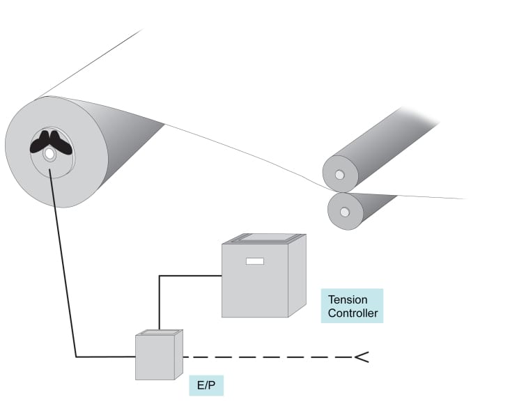
The unwind brake operates much like the brake on a car, with disk, calipers and pads. The tension is linked to a position controller.
During the operation of any converting machine, whether for film, foil, wire, paper or board, plus most large printing presses, rolls of materials are handled by unwinds, often still driven by pneumatically operated braking systems. The traditional tension control system for an unwind stand is a simple mechanical brake. In principal, the unwind brake mechanically operates much like the braking system on your car, with a disk, caliper and pads, but is controlled by a tension sensor linked to a setpoint controller. As the roll unwinds, the tension is maintained by the brake for smooth passage of the material through the dies or rollers, resulting in better package alignment, less wrinkling, better print registration, even more consistent wire dimensioning and other production positives. These mechanical brake unwinds are effective in controlling the tension, but have inherent problems of heat and power loss, plus mechanical wear and constant maintenance needs, substantially impacting machine uptime.
The typical mechanical brake is pneumatically controlled and may utilize several sets of friction pads to control the web tension as the roll dimension decreases. Plus, a reasonable pressure range in many applications might be from 15-90psi or a 6:1 drop, a range significantly less than the core to full roll ratio for most jobs, an obvious inefficiency in operation.
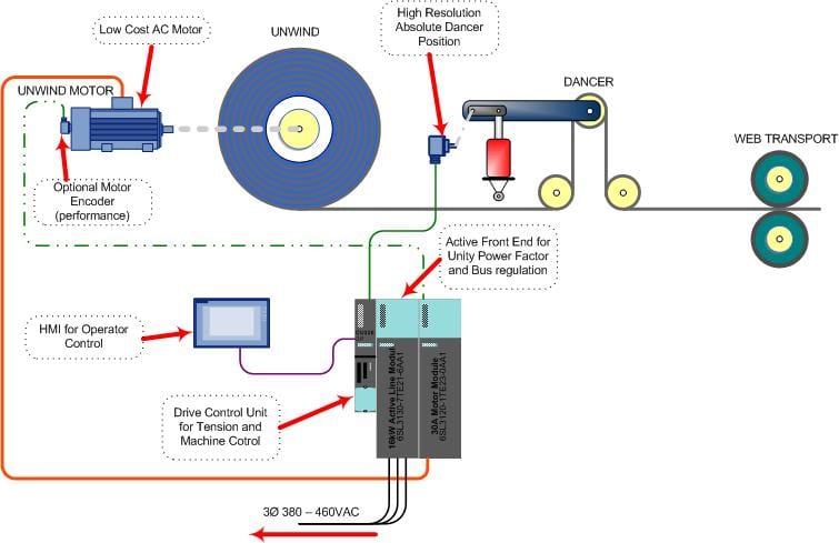
This schematic shows the typical driven unwind system in operation
To affect good tension control on the brake, these friction pad sets need to be manually changed in an out of the brake assembly, depending on the desired operating tension and the roll diameter changes involved. Often, the adjustments are several per roll during this manual changeover. Because the mechanical brake creates the unwind tension through friction, it generates substantial heat and often requires a separately powered fan for cooling to operate effectively. This friction also means the pads are subject to rapid wear, requiring frequent and time-consuming changes or maintenance checks.
For almost a decade now, this old technology has been gradually replaced, though usually in the lower power ranges, by newer precision technology, involving AC motors, drives and electronic loadcells. On converting lines today, a further leap forward is being made with the onset of active front end technology.
With such technology, the operating principle is as follows.
Conventional mechanical brake system
Since the unwind application is regenerative (regen) in nature, a driven unwind needs to return the energy that the mechanical the brake produced as heat back to the AC line. In the past, regen DC drives have been successfully applied as driven unwinds, but DC drive systems are no longer common and even during their prime were very costly. Early in the AC drive technology for these applications, the drives did not have the capability to regenerate the power back to the AC line and, when applied as unwind brakes, required regen resistors to dissipate the tension energy. This was wasteful and costly.
Today’s AC drive systems now have the technology to regenerate the energy back to the AC line just as the DC drive did, but with added benefits to the user and machine designer alike. Sending the tension energy back to the line means power that once was wasted can now be retained, instead of the system producing heat and worn parts. When the drive is equipped with active front end technology, it will return the previously wasted energy with near unity power factors, something not possible for any DC drive system.
Even an open loop AC drive motor combination offers a tension control range far beyond the limits of a pneumatic braking system. Synchronous AC motors can offer precision open loop torque control without a tension sensor, thereby saving further cost and inventory. Today’s highly accurate tension control systems can be designed with high resolution (sin/cos) feedback encoders on both the unwind motor and dancer position feedback. Additionally, in more advanced active front end designs, the regen capability of the drive can actually assist in the increase of stopping times and tension control regulation, owing to the four quadrant control, i.e., the motor can sink or supply current to the motor in both directions.
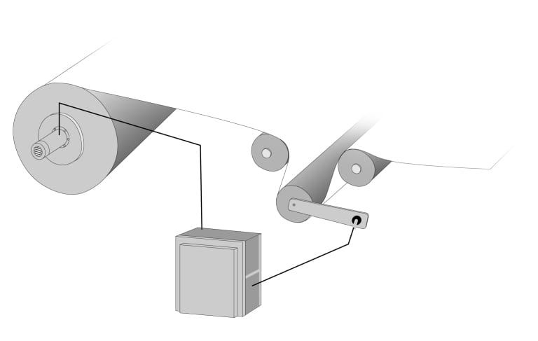
Driven unwind with AC regen motor, drive
AC regen drive systems can also offer today’s machine designer software configurations with a wider range of control flexibility. They can be configured to operate in the most basic mode with no motor encoder or with tension feedback to system configurations, utilizing either dancer position sensors or loadcells. Alternatively, they can function as a programmable logic controller (PLC), controlling the machine functions on the unwind, while also connecting directly to a human-machine interface (HMI) panel. In most converting, packaging and printing applications, the dancer position sensor can be used to calculate the starting diameter of a roll, eliminating additional diameter sensors and the possibility of operator error in the roll diameter input. Further enhancements for unwind spindle motion such as jog for threading have also emerged for operator convenience through active front end technology.
Beyond the obvious cost savings of pad replacements on mechanical braking systems, AC motors are virtually maintenance free by comparison to DC motors, as AC motors have no brushes, do not require controller contactors to reverse direction of motor rotation or have commutators. Fewer moving parts invariably means less motor maintenance, for additional cost and time savings.
In the most advanced systems, common DC bus regulation, energy-monitoring devices for near unity power and, through the use of mechatronic services often provided by the manufacturers, “turn off” parameters in vector drives are possible. Mechatronic services can also be utilized for the proper tuning of these drives onsite or during machine build. For designers, such services further assist in the proper sizing of motors, based on the mechanical and electrical forces generated by machine operation or computerized simulation of it.
This combination of improved operation, reduced maintenance, motor power savings and conservation of nearly all energy within the system make AC regen drives with active front end technology a decided advantage for machine designers and end users of converting, packaging, printing, wireforming and other roll-fed machinery, where driven unwinds can be implemented.
For more information on regenerative drive motors and systems, please contact:
For product information and inquiries, call +1 800 879 8079 ext. Marketing Communications or e-mail SiemensMTBUMarCom.industry@siemens.com.
Continue readingIntegrated drive system provides OEMs and end-users cost-effective Simotics motor and Sinamics drive packages from single source; backed by three-year warranty
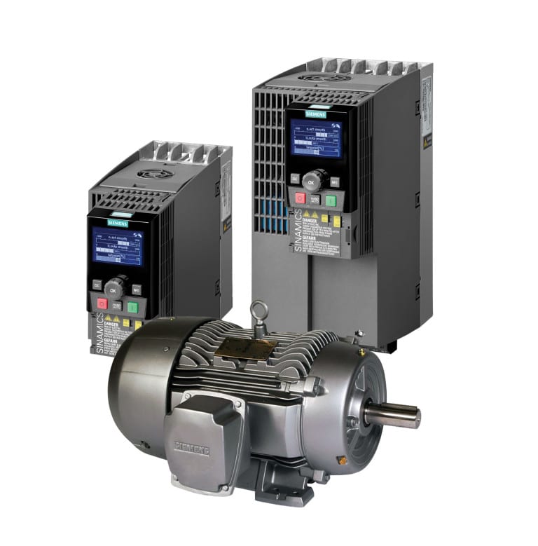 Siemens Industry, Inc. announces the release of combination motor/drive packages, allowing an OEM or end-user the option to select the optimum solution for a variety of heavy-duty industrial motion control applications from a single source, backed by a full three-year warranty. Choosing from a predetermined list of motor/drive combinations, the customer simply makes the selection best suited to the application. The motor and drive are packaged on a single pallet, shipped and invoiced together.
The motor and drive combinations are power-matched for 480V high-overload operation through a 20 hp range, with I2T protection from thermal damage provided as a standard in both the motor and the drive components. The Siemens Intelligent Operator Panel (IOP) is included with these packages, allowing easy step-by-step drive start-up.
Application macros are provided in the Sinamics G120C drive for easy installation and wiring; the terminals are pre-assigned at the factory and the parameters are automatically set. The SIMOTICS SD100 motors are rugged cast-iron with inverter duty ratings in a 4:1 speed range for constant torque and 20:1 speed range for variable torque. Simotics SD100 units are severe-duty TEFC motors that meet NEMA Premium® efficiency.
Communications selections on these matched motor/drive combinations include RS485 with USS and Modbus protocols. A Profibus variant is also offered for a Totally Integrated Automation (TIA) solution. TIA is the proprietary Siemens solution for achieving optimum performance, energy efficiency and sustainability within a machine or manufacturing environment.
Standard pricing has been established for a wide variety of motor/drive combinations from 1–20 hp and is included in the available literature on this new Siemens service.
For more information about these combination motor/drive packages, visit www.usa.siemens.com/drives.
For product information and inquiries, call +1 800 879 8079 ext. Marketing Communications or e-mail SiemensMTBUMarCom.industry@siemens.com.
Continue reading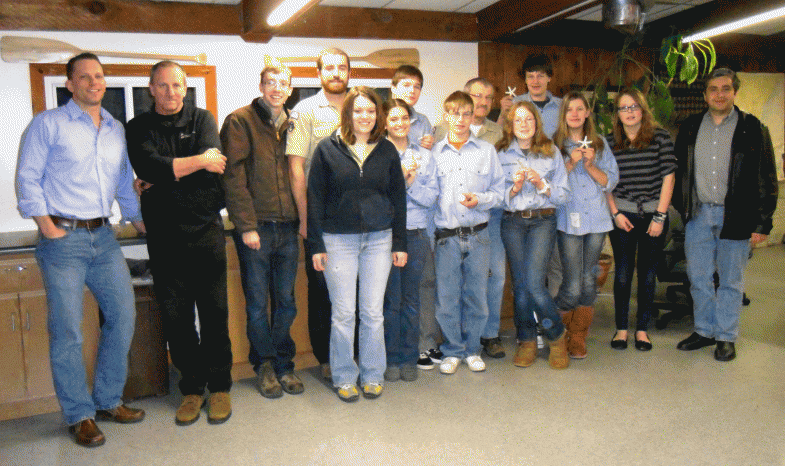
Steve Sikorski from Magma (far left) led the teaching experience for the Racine, Wisconsin Sea Scouts, as they learned about metalcasting.
In March 2013, representatives from MAGMA Foundry Technologies used the Foundry in a Box, donated by AFS, to teach the Racine, Wisconsin Sea Scouts, Ship 5750, about metalcasting. Sea Scouting is a division of the Boy Scouts of America for young men and women between 14 and 21 years old. The group focuses on developing future leaders through developing maritime skills, both on and off the water. The Scout group devotes their summer activities to sailing and their winter activities to learning manufacturing skills to produce useful items. Previous projects included land sailing vessels, a pig roaster and rebuilding engines for use in boats.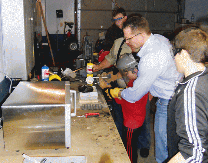
During this past winter, the scouts focused on developing their metalworking skills by making wind vanes using welding, grinding, machining and plasma cutting technologies. This project had all the Scouts excited about metalworking and it created a great opportunity to expose them to metalcasting technology, where Magma is the market leader in casting simulation and process optimization for foundries worldwide.
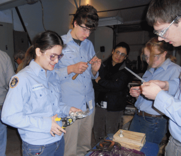 The meeting was kicked off with a short presentation about metalcasting and how this 6,000-year-old process relates to products the Scouts use every day. The Scouts were then allowed to get started with a hands-on project, with each Scout creating a mold, melting the metal, pouring the casting and cleaning the castings. Some Scouts used the standard patterns that came with the Foundry in a Box, while others were more adventurous and tried making their own patterns, one being sea shells. A final presentation was made, tying in this age-old process with advanced casting process simulation technology to show what occurred inside the mold during the making of the Liberty Bell casting.
For more information on this story, please contact:
Christof Heisser
President
MAGMA Foundry Technologies, Inc.
10 N. Martingale Road, Suite 425
Schaumburg, IL 60173
Phone 847-969-1001, ext. 225
Email cheisser@magmasoft.com
Web www.magmasoft.com
 SIGMA Plastic Services will partner with RJG to provide a detailed training session to educate plastic injection molding professionals on cutting edge technologies that will assist in more successful product launches.
Working together with RJG at the Medical Devices conference, the goal is to provide attendees with a demonstration on how to utilize currently available technology to their best advantage. Reducing time to market with higher quality and repeatable molding processes are key to the future success of injection molding professionals and OEM’s.
RJG and SIGMA will take you through the critical steps from product design to production with best practices for successful, profitable molding. Develop and merge the part design, the polymer, the mold, and the process in a virtual production environment where all of the critical aspects related to profitable part quality can be evaluated and optimized before the actual mold is ever built.
This is an actual workshop with worksheets and exercises that can be used to develop improved communications within your work environment.
 What areas of the part design are the most critical?
Should the mold insert be P20, H13, or a Cu based alloy?
Where are the most critical areas for cooling?
What will the cycle time be?
Is the distortion related to fiber orientation or temperature?
Can it be controlled with packing?
Will it be pressure limited when the viscosity shifts?
How big is the process window?
Can the process be maintained?
Where do we need sensors?
How to contain parts produces outside of the process window
 Virtually develop and optimize the mold and the process together, before the mold is ever built. Verify the appropriate molding machines are capable and available. Ensure the best process is developed, used and repeated, in spite of day to day variation in the production environment.
If the mold is already built and the part dimensions from the quoted 30s cycle are out of spec, what are you going to do about it, other than lose money…..? There are more profitable ways of doing things.
For more information, contact:
Matt Proske
Vice President
SIGMA Plastic Services, Inc.
10 N. Martingale Road, Suite 425
Schaumburg, IL 60173
Phone 847-558-5602
Email contact@3dsigma.com
Web www.3dsigma.com
Gümmilast material from Kastalon offers metalformers greater levels of performance and wear characteristics, compared to conventional polyurethane or Neoprene forming pads and fluid cells.
Short run forming of complex sheet metal shapes using rubber dies and pads is quick and highly effective. This technique was first accomplished using the Guerin Process. After the Second World War, the Wheelon process was developed as an improvement over the Guerin Process. A Wheelon press is capable of manufacturing large, complex, short run parts with economic tooling. This type of hydraulically actuated bladder forming is widely used in the aerospace industry today.
When the Wheelon process was first employed, the forming press fluid cells and forming pads were made of Neoprene rubber. The Neoprene formulations of the day were developed by rubber molders’ chemists. Their formulas were proprietary and highly secretive.
The high grade formulation of Neoprene used was an excellent material for the function of forming pads and fluid cells. It was tough, had very high extensibility, good cut resistance, excellent oil resistance and produced good detail with moderate pressures.
This was the standard material for Wheelon forming pads and fluid cells for many years. However, as the U.S. industrial rubber goods industry matured, its productive capacity diminished. The industry lost the capacity and knowledge required to make Neoprene pads and cells. There are presently no suppliers of rubber Wheelon or Guerin cells or pads in North America.
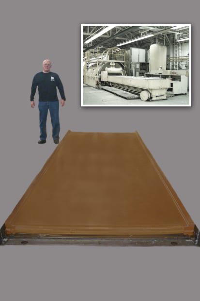
Product shown in use in the Wheelon process, one used extensively in the aerospace and other industries.
Fortunately, there was capacity to produce these parts from polyurethane. Polyurethane is a synthetic elastomer that is far stronger than Neoprene. Polyurethane has greater cut resistance, more abrasion resistance, greater tensile strength and has suitably high elongation for effective use in the Wheelon process.
Polyurethane is also a more environmentally stable material than the original Neoprene. Most often, when installing forming pads and upon starting forming operations, the Neoprene would be “dried out”. This would lead to shrinkage of the pad and increased stiffness. In order to install the pad and/or start the operation, it would be necessary to heat the Neoprene to restore it to its original softness and resilience. Polyurethane is far more consistent, retaining its size, shape and maintaining its softness and resilience. This eliminates the need for heat “rejuvenation”.
However, in spite of the superiority of the physical properties of polyurethane over the previously used Neoprene, there is a drawback to polyurethane. Due to its increased strength and toughness, far greater pressures must be employed to achieve acceptable part definition and this results in greater strain on the press, its components and some reduction in forming definition.
Some of the difficulties encountered with the use of commercial and even Kastalon KAS43210AE forming pads and cells are:
The challenge to industry has been to create a material that has polyurethane’s toughness and the extensibility of the lost Neoprene material.
Our initial discoveries led us to improve the traditional polyurethane formulations to increase extensibility, reduce working pressure and improve cut and tear strength in the “mid extension” ranges where these pads operate. However, this was only a compromise and a temporary solution to producing a forming pad with superior performance.
After years of continuing research, a hybrid polyurethane compound, trademarked Gümmilast by Kastalon, has been developed. The properties of Gümmilast are very similar to the original Neoprene in performance and exceed the toughness of traditional polyurethane. A comparison of the original Neoprene, Gümmilast, Kastalon KAS43210AE and commercial polyurethane is presented in the following table.
Physical Properties: Traditional Neoprene vs. Polyurethane
| Neoprene | Gümmilast KAS021909A | Kastalon KAS43210AE | Commercial PUR | |
| Hardness,Shore ATensile, psi | 55-602,002 psi | 602850 | 704153 | 704660 |
| Elongation | 773 % | 774 | 694 | 630 |
| 25% modulus | 92 psi | 133 | 201 | 221 |
| 50% | 119 psi | 184 | 260 | 282 |
| 100% | 157 psi | 229 | 340 | 360 |
| 200% | 277 psi | 262 | 434 | 475 |
| 300% | 472 psi | 337 | 522 | 670 |
| 400% | 741 psi | 471 | 738 | 985 |
| Split tear | 228 psi | 191 | 181 | 185 |
| Dynamic modulus | 289 | 372 | 733 | 836 |
The similarity between Gümmilast and the original Neoprene is apparent. In the operating range extension (250-400%), previously available polyurethanes create far higher internal stresses. The rapid increase of these stresses in this operational strain range leads to need for higher pressure and less definition. This makes tool design and the use of intensifier pads highly critical.
When using Gümmilast, the reduction in operating pressure will yield greater press life, while offering greater part definition.
Life testing of Gümmilast pads and cells is ongoing. To date, Kastalon anticipates 3-6 times the life of Improved Kastalon Polyurethane and an even greater life over commercial polyurethane.
In conclusion, Kastalon Gümmilast will provide the Wheelon Process user with a material that offers similar process ease, forming definition and reparability as experienced with the original rubber and providing significantly improved life over commercial polyurethane. Gümmilast is also available for hydroforming bladders, throw pads and Guerin Process pads.
Kastalon Gümmilast products are available from your press parts provider or from Kastalon, Inc.
For more information on this product, please contact:
KASTALON, INC.
4100 W. 124th Place
Alsip, IL 60803
Phone: 708-389-2210
Fax: 708-389-0432
Web: www.kastalon.com/engineering-guide.php
Email: sales@kastalon.com
Attention: Marty Pokorney