
Contact us today:
Author Archives: Bernard and Company
Siemens Names Two to New Posts
By Bernard and Company
No Comments
Matt Lorig
Machine Tool Business appoints new business development manager for Asian builder relations plus dealer support manager for Eastern U.S.
May 15, 2012 — The Siemens Machine Tool Business, part of the Drive Technologies — Motion Control group within Siemens Industry, Inc. has appointed Matt Lorig as business development manager for the company’s Asian builder base. As such, Lorig will engage in direct sales of the company’s CNC, motor and drive packages to Asian builders and importers in North America, plus maintain existing business in a response mode to better serve this growing customer segment for Siemens. Matt brings over 20 years in industrial automation to this new position, much of it in the machine tool industry with a major Japanese supplier. He has expertise in CNC, robotics, servo technology and general motion control.

Chris Pollack
In related news, Christopher Pollack assumes the duties of dealer support manager for the Eastern United States. His primary responsibility will be field support for the growing dealer network in the region that sells machine tools with Siemens CNC technology onboard. This will include technical CNC training, software support and hands-on utilization demonstrations for dealer customers, both onsite and at dealer events. Chris brings extensive knowledge of CNC technology to this position, plus a working knowledge of MasterCam and SolidWorks. He is a certified Class A machinist and was most recently an applications engineer at Fryer Machine Systems.
For more information on the this story, contact:
Siemens Industry, Inc. Drive Technologies — Motion Control (Machine Tools)
390 Kent Avenue Elk Grove Village, IL 60007
Phone: 847-640-1595
Fax: 847-437-0784
Web: www.usa.siemens.com/cnc
Email: SiemensMTBUMarCom.industry@siemens.com
Attention: John Meyer, Manager, Marketing Communications
Follow us on Facebook: www.facebook.com/SiemensCNC or Twitter: www.twitter.com/siemens_cnc_us.
—
Siemens Industry Sector is the world’s leading supplier of innovative and environmentally friendly products, solutions and services for industrial customers. With end-to-end automation technology and industrial software, solid vertical-market expertise, and technology-based services, the sector enhances its customers’ productivity, efficiency and flexibility. With a global workforce of more than 100,000 employees, the Industry Sector comprises the Industry Automation, Drive Technologies and Customer Services Divisions as well as the Metals Technologies Business Unit.
The Siemens Drive Technologies Division is the world’s leading supplier of products, systems, applications, solutions and services for the entire drive train, with electrical and mechanical components. Drive Technologies serves all vertical markets in the production and process industries as well as the infrastructure/energy segment. With its products and solutions, the division enables its customers to achieve productivity, energy efficiency and reliability.
Continue reading
Gisma Steckverbinder GmbH: Well-Connected
By Bernard and Company
No Comments
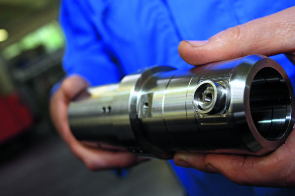
A variety of complex underwater electrical connector casings are made by Gisma, using Siemens Sinumerik CNC-controlled Spinner lathe technology.
Gisma specializes in the production of underwater connectors typically used in offshore energy generation. Siemens Sinumerik-controlled Spinner CNC machine tools contribute significantly to the success of the company.
Special connectors are required to safely and reliably connect electrical and fiber-optic cables deep underwater. With maintenance more difficult, all of the parts must meet the most rigorous technical requirements in terms of reliability and service life. Products from Neumünster, Germany-based Gisma Steckverbinder GmbH are designed to be fail-safe and to withstand maximum pressure loads, while still operating on the basic “push and pull” principle. In addition to shipyards, the offshore oil and gas industry, and the military, Gisma is now receiving an increasing number of orders from offshore energy companies. Gisma works closely with its customers on all of its developments – most recently on a single-pole, wet-mateable power connector for use in offshore underwater turbines, which was designed to handle operating voltages of 12 kV at 400 A and is guaranteed to be fail-safe for 25 years.
Manufacturing repeatability to the nearest micron
To meet the high standards required in underwater technology, manufacturing accuracy to the nearest micron is required, especially for fiber-optic connectors. In addition, the materials must all be corrosion-resistant. The highest levels of functional safety are also required to enable the machining of seawater-resistant bronze and stainless steels, along with more sophisticated materials such as duplex and super-duplex steels, titanium and high-performance plastics. The demands placed on the cutting machines and controllers used in the production of these parts are correspondingly high. For many years, Gisma has relied on Spinner milling and turning centers equipped with Siemens Sinumerik CNCs. “The machines rarely fail, mostly because of the high-quality drive and control technology,” says production manager Michael Königsmann. He is particularly impressed by the TC77 universal turning machine from the 800 series, which will be used, among other purposes, to turn the casings for a new high- performance connector measuring up to 3000 mm long. The TC 77 is built on a rigid Meehanite cast iron base with large tempered steel guide rails, allowing a high cutting capacity, along with good damping and rigidity characteristics. It is equipped with a water-cooled motor spindle, which allows precision turning to within a few hundredths of a millimeter, shortly after switching on. The machine also has a counter spindle and features 12 tool stations with driven tools. “This lets us manufacture some workpieces in a single run, whereas previously it would have taken several,” explains the production manager. In accordance with VDI/DGQ 3441, the machine achieves repeat accuracy of 2 µm in the x- and z-axes.
Consistent CNC strategy since 2000
The sophisticated Sinumerik 840D sl CNC plays an equally important role in reducing manufacturing time. Since the year 2000, Gisma has used only Siemens controllers in its production facility. “By standardizing the controller, we have created an environment where we can deploy our employees flexibly all over the shop floor and operator error has become a thing of the past,” explains Tobias Frerck, Gisma’s managing director. “We have always had great results with Sinumerik controllers and knew we could rely on our competent regional service partners on those rare occasions when something went wrong.” For newly developed products, production manager Königsmann and his staff usually create the CNC programs on external PCs in DIN ISO and then send them over the network to the most suitable machine. If there is a need to manufacture new connectors based upon an existing family of parts, the required CNC programs can usually be adjusted directly on the machine itself. And, just as during initial setup, the Sinumerik 840D sl’s fully integrated and user-friendly ShopTurn software comes into its own here. The animated graphical user interface is completely intuitive, meaning that it can be easily picked up even by temporary staff. The Sinumerik Safety Integrated software package provides additional safety when working in setup mode, allowing operators to monitor the production process with the machine door open. Safety mode allows speeds of up to 2 m/min, and the software ensures that the drives stop quickly after a maximum of 1 to 2 mm, should any problems arise. If anything is unclear when an operator is entering data, he or she can push a single button on the operator console to bring up a help menu. Switching to a text-based DIN interface is just as straightforward, for example, when an experienced programmer feels that he or she can more quickly and easily describe a complex contour using a DIN statement. As always, the main focus remains on achieving the highest possible standards in terms of both the manufacturing and the finished product.
For more information on this article, please contact:
SIEMENS INDUSTRY, INC.
DRIVE TECHNOLOGIES
MOTION CONTROL
MACHINE TOOL BUSINESS
390 Kent Avenue
Elk Grove Village, IL 60007
Phone: 847-640-1595
Fax: 847-437-0784
Web: www.usa.siemens.com/cnc
Email: SiemensMTBUMarCom.sea@siemens.com
Attention: John Meyer, Manager, Marketing Communication
Follow us on Facebook: www.facebook.com/SiemensCNC or Twitter: www.twitter.com/siemens_cnc_us.
—
Siemens Industry Sector is the world’s leading supplier of innovative and environmentally friendly products, solutions and services for industrial customers. With end-to-end automation technology and industrial software, solid vertical-market expertise, and technology-based services, the sector enhances its customers’ productivity, efficiency and flexibility. With a global workforce of more than 100,000 employees, the Industry Sector comprises the Industry Automation, Drive Technologies and Customer Services Divisions as well as the Metals Technologies Business Unit. For more information, visit http://www.usa.siemens.com/industry.
The Siemens Drive Technologies Division is the world’s leading supplier of products, systems, applications, solutions and services for the entire drive train, with electrical and mechanical components. Drive Technologies serves all vertical markets in the production and process industries as well as the infrastructure/energy segment. With its products and solutions, the division enables its customers to achieve productivity, energy efficiency and reliability. For more information, visit http://www.usa.siemens.com/drivetechnologies.
Continue readingUniversal Turning Solutions for Manufacturing Companies
By Bernard and Company
No Comments
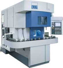
The VL 5i Vertical Turning Machine from EMAG has been designed for the quality- and cost-conscious medium-sized business and the sub-contractor: a production aid that can be used universally and that impresses by its small footprint and its highly advantageous price-performance ratio – including automatic workhandling.
Better component quality at a lower price? VL 5i, a vertical turning machine that is custom-made to fully meet the demands of the small and medium size manufacturing company.
With their VL 5i the machine tool specialists at EMAG have developed a comprehensive solution for small and medium size manufacturing companies. It can be used for small and large batch production, and complete-machines workpieces of up to 250 mm in diameter in a single setup. Flanges, gears, gear shafts and steering pinions can be machined with as much efficiency and to the same quality as brake disks or cams. The machine features a powerful 28 kW workspindle with a top torque of 300 Nm, plus a turret that accommodates turning as well as driven tools and has an impressively short indexing time of 2.2 s.
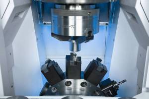
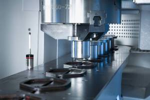
Machining area of the VL 5i: 12 turning or up to 12 driven drilling and milling tools allow you to carry out a great variety of operations in a single set-up.
Drilling and milling operations can be incorporated by equipping some or all of the 12 turret stations with driven tools. The outstanding feature in this is the EMAG turret drive that combines high speeds with outstanding performance and a small space requirement. For instance, the diameter of the turret is only 360 mm but accommodates 12 stations and has a maximum torque rating of 45 Nm.
Flexible automation included
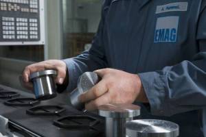
Flexible component loading: workpieces are loaded by inserting them directly into the carrier prisms or, where necessary, into workpiece receptors that can then be inserted into the prisms.

A recirculating conveyor band with carrier prisms that do not need to be reset, takes the components to the pick-up station. As this station lies behind the machining area, the operator is able to remove finished components and insert new raw-parts at the front of the machine.
Proof of the outstanding quality of the VL 5i is, first of all, its integrated automation system. It uses a recirculating chain conveyor equipped with carrier prisms that deliver the raw-parts directly to a pick-up station for machining. This station is located behind the machining area, so the operator can – at any time – insert new raw-parts at the front of the machine. It is hard to imagine a more flexible and, at the same time, more universal solution for the automation of a machine tool.
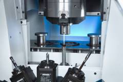
Short travel times = short idle times
Quickly in and out: the workpieces reach the pick-up station in flexible carrier prisms mounted on the recirculating conveyor belt, with the flexibility of the prisms minimising the resetting effort for different workpiece diameters.
Another advantage of the VL 5i is its short idle times. Changing workpieces is a very fast process, because the distance between the loading position and the machining position is only 550 mm. The importance the EMAG turning specialists attach to the machine’s efficiency can also be seen in the design of the guideways. They are located outside the machining area, where they are protected against chips and dirt. This reduces the maintenance effort and makes the machine less susceptible to breakdowns. The machine can also be equipped with an optional measuring station, located outside the machining area. Here the component is measured on its way from the tooling zone to the unloading station, while still in its original clamping position. The measuring results are not distorted by the entrance of chips, as the vertical turning operation provides for ideal chip flow conditions.
Energy efficiency is very important
The sustainable use of energy and resources completes the picture of an engineering solution that not only offers a small footprint but also eliminates unnecessary design details which is the reason why the machine builders at EMAG can offer this machine at an advantageous price-performance ratio.
Optional measuring: a measuring probe, located outside the machining area, brings quality assurance to the machine. In automated measuring cycles, carried out between machining process and component removal, the VL 5i logs the offset data and provides a record for quality assurance purposes.
For more information:
EMAG LLC
38800 Grand River Avenue
Farmington Hills, MI 48335
Tel: (248) 875-0313
Fax: (248) 477-7784
E-mail: info@usa.emag.com
Web: www.emag.com
Attention: Peter Loetzner
Continue reading“Energy Efficiency Award”: The ZF Group Honors EMAG Commitment
By Bernard and Company
No Comments

Award-winning – the VL 2 from EMAG is one of the most energy efficient machines in the world.
According to the “Future Panel” of the IW – the Institut der deutschen Wirtschaft (Institute for German Economic Research) – energy efficiency is becoming increasingly more important in the metalworking industry. The IW suggests that over 60 percent of the companies interviewed for the award are hoping for “a push forward toward innovation”. EMAG is an initiator of such innovations. Its experts develop machine tools and production processes that consume significantly less energy then its competition. In honor of this, EMAG has received the “Energy Efficiency Award” from the ZF Group. This award states that EMAG’s contribution has been honored as one of the top five.
From their efficient manufacturing technology to economical design and construction, the machine builders at EMAG have shown their in-depth know-how and experience in one of the most important fields of industrial development, to compete for the “Energy Efficiency Award” from ZF. The result convinced decision makers at ZF and EMAG’s competition entry called “Energy-efficient Production Machines” has been honored as one of the “Top 5 Projects“. In fact, in this particular sector EMAG was the only machine builder honored. Before the competition as part of its “Year of Energy”, ZF contacted approximately 600 of its suppliers, inviting them to participate in the competition. From 30 eligible entries, the specialists in driveline and chassis technology picked the top five. These five companies were invited to present their particular approach to efficiency on September 13th at ZF, Saarbrücken.
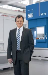
Dr. Guido Hegener, Managing Director EMAG Salach Maschinenfabrik GmbH
EMAG has been focusing on energy efficiency for years
“We are very pleased to have received this award”, declared Dr. Guido Hegener, Managing Director of EMAG Salach, Maschinenfabrik GmbH. “It is an incentive for us to continue on the chosen path. Our focus has been on energy efficiency for years.” During his presentation Dr. Hegener highlighted the various developments at EMAG:
- Attempt to replace less economical processes, such as the traditional grinding process, with more energy-efficient manufacturing methods, such as scroll-free turning or hard turning. With these processes the energy requirement is up to 90 percent less. “Cycle times for these processes are noticeably shorter and the runtime of auxiliary equipment is reduced. This brings massive energy savings”, explained Mr. Hegener.
- EMAG engineers are also breaking new ground in the design of manufacturing systems. Within the framework of a collaborative research project, a software package was developed that allows for the energy consumption of machine components and complete systems to be determined at the development stage, on a computer.
“We have established how much energy each component consumes and where the biggest potential for savings lies”, explained Wolfgang Rummel, Head of Control Technology Development and Design at EMAG Salach Maschinenfabrik GmbH. He also referenced the concrete measures taken: EMAG includes the most efficient components in their standard machine design – for instance hydraulic packs with greater efficiency, low-wattage valves and intelligent auto-standby circuitry.
At the end of his competition presentation Dr. Hegener introduced a new overall objective: the development of the “sustainable factory”. He suggested that in future the production – together with the building in which it is situated and its technological contents – will be evaluated as a single entity. In conclusion, he expresses his belief that the measures taken to reclaim and recycle energy can lead to a potential saving of up to another 40 percent.
 (text translation from above)
SAVINGS POTENTIAL PLATFORM 2
46.9% over existing machines
9.6% – optimization cooling systems
8.0% – hydraulics (e.g. DvP units)
6.9% – drive cooler with through-hole technology (only on Fanuc)
6.6% – reduced air seal, system pressure pneumatics
6.6% – standby circuitry
3.2% – IE2 motors (IE3 option)
1.9% – low-loss gear motors (option)
1.8% – frequency-controlled auxiliary drives (option)
1.7% – timed relief valves, flat-jet nozzles (options)
0.6% – low-wattage valves
53.1% – remaining machine consumption
At EMAG energy efficiency comes as standard.
Energy savings are implemented on the machines with Platform 2, as compared to similar earlier models = 46.9%.
For more information:
Kristal Kilgore
EMAG LLC
38800 Grand River Avenue
Farmington Hills, MI 48335
Tel: (248) 875-0313
Fax: (248) 477-7784
E-mail: kkilgore@emag.com
Web: www.emag.com
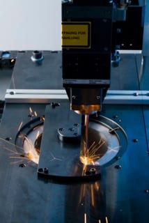
Of Utmost Precision and Highly Productive: Laser Welding In “Transmission Manufacture 2.0”
By Bernard and Company
No Comments
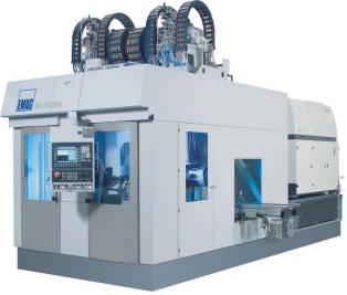
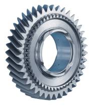
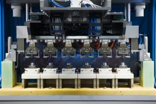
The ELC 250 DUO – a compact laser welding cell for the machining of differential housings. The DUO variant features two spindles. The twin-station operation allows for cycle time-concurrent loading and unloading of the work spindles.
“From Dual-Clutch Transmission to the classic differential: modern transmission technology is a pivotal research sector in the automotive industry. With new materials and altered geometries, designers optimize the functionality of the different gearwheels. Furthermore, these wheels are required in ever larger quantities, owing to the fact that the number of speed-gears in many passenger cars is on the increase. The innovations that promote the effectiveness of the production processes being applied include, for example, laser welding. With their ELC series of machines, the specialists at EMAG have developed integrated solutions for the application of processes with high output rates. The company’s in-depth knowledge of the production processes used for many transmission components has added to its competency in machine development.
(See the video HERE)
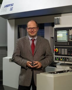
Herr Dr Andreas Mootz is Managing Director of EMAG Automation GmbH, Heubach, and responsible for the development of the production laser welding technology.
A first glance at a typical transmission component makes it plain where the challenges lie: even a small wheel with integrated synchronous gearing represents a relatively complex design. To manufacture it efficiently and at the highest precision calls for the two different parts to be produced separately and subsequently joined in a joining+welding process. It is at this point in modern transmission manufacture that laser welding comes into its own”, explains Dr. Andreas Mootz, Managing Director of EMAG Automation. “The process allows you to concentrate a carefully dosed amount of the energy emitted by the laser beam on the welding point, minimizing possible warping, while still achieving high welding speeds.” Furthermore, the welding process from EMAG uses solid-state lasers of outstanding energy efficiency. Whereas a classic carbon dioxide laser will achieve an efficiency factor of just about eight percent, the EMAG specialists can rely on an efficiency factor of approximately 20 percent with their technology. In other words, the power used to achieve the same optical performance is noticeably less, with energy costs in the production department massively reduced.
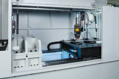
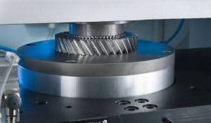
Machining area of the ELC 160 Laser Welding Machine for the welding of gearwheels. On up to three stations, the wheel assembly is pre-heated, joined and laser welded.
Stationary welding device scores heavily
Similarly effective within the total process is the integration of different production sequences on the ELC system. For starters, the work spindle uses the pick-up principle to load itself. The components involved are then clamped and pressed together in the joining press. The clamping technology used ensures the highly accurate positioning of the components, providing ideal conditions for the welding process. The design of the stationary optic ensures great operating safety and optimal stability of both machine and welding process. Depending on the workpiece material, the components can be induction-preheated prior to the welding process and brushed after it – and whatever is required, the process is completed in a single setup. The complete joining+welding process for a gearwheel takes just 12 seconds. This ensures that the components for a differential are thus finish-welded within no more than 40 seconds.

Laser welding the differential housing and the crown gear has meant a weight reduction of 1.2 kg or 2.65 lbs for this assembly.
Laser welding leads to advances in lightweight construction
The differential housing, as an example, clearly shows the possibilities the laser welding technology opens up in the general development of vehicle production. For some time now, automotive companies have been replacing the screw-type connection between differential housing and crown gear with a welded seam. The result: the cost of materials reduces and the weight of the assembly falls by approximately 1.2 kg or about 2.65 lbs. “When looking at the advances made in lightweight construction in the automotive industry, this kind of savings means the world”, explains Dr Mootz.
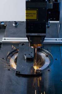
Laser welding a synchronous wheel onto a gear. The new fibre laser on the ELC 160 cuts operating costs in half.
The customer benefits from practical knowledge
Seen in context, the welding specialists from EMAG Automation in Heubach, Germany are able to look back on a truly impressive history of success. Over 50 ELC systems have been sold in the last decade. All leading automobile manufacturers are using them. EMAG is a world leader in solid-state laser systems for the production of transmission and powertrain components. How did this success come about? “It is of decisive importance that we have at our disposal a large reservoir of know-how in the manufacture of these components. We understand the entire manufacturing process, from turning and grinding, and from welding right up to the concluding ultrasound testing process”, emphasizes Dr Mootz. “We can develop and construct the whole of the process chain. This significantly simplifies the planning of new production sites and the expansion of existing ones.“
Laser-welded gearwheel
General market development is positive
The general market development does play into the hands of the German machine builder: It is not only the successful dual-clutch transmission that ensures the need for more gears. Conventional transmission systems also tend to have more speed gears, as this reduces gas consumption and improves the driving comfort. “Having said that, we are offering a well proven welding technology that provides an energy-saving, high-precision manufacturing process and, at the same time, helps to advance lightweight construction and reduce production costs. This is no doubt a very successful and persuasive combination”, concludes Dr Mootz.
Joining a gear and a synchronous ring on the ELC 160.
For more information:
EMAG LLC
38800 Grand River Avenue
Farmington Hills, MI 48335
Tel: (248) 875-0313
Fax: (248) 477-7784
E-mail: info@usa.emag.com
Web: www.emag.com
Attention: Peter Loetzner
Continue readingNew Technologies for Challenging Workpieces
By Bernard and Company
No Comments
Increasing demands made on precision and the push for the decrease of price of modern components is pushing traditional manufacturing processes. EMAG offers three production technologies that complement or replace traditional processes such as turning, milling and grinding.
PECM for nickel- and titanium-based alloys

The ECM process is used to deburr components only at the points where material needs to be removed, and without it having any mechanical or thermal impact on the workpiece.
With its PECM technology (Precision Electro-Chemical Machining) EMAG presents a production process that opens up completely new fields of application. PECM is a process for the machining of high-alloyed materials, such as nickel- and titanium-based alloys. The disadvantages of traditional metal cutting – tool wear, mechanical stresses, micro-fissuring caused by heat, oxidization layering and the need for subsequent deburring operations – are eliminated, because this process is a non-contact one without heat input. All electro-chemical machining processes are characterized by stress-free material removal, smooth transition points and surfaces without ridge formations.
The ECM process is used to deburr components only at the points where material needs to be removed, and without it having any mechanical or thermal impact on the workpiece.
The advantages that the PECM process provides for different branches of industry are best shown with the example of a turbocharger for the automotive industry. The electro-chemical process is one that can be used to effectively in the machining of many high-alloy components, especially those in the high-temperature sector of the turbocharger – it also offers a much shorter and very efficient process chain. The typical clean-up operations necessary when traditional machining processes are used – such as deburring after milling – are no longer necessary. PECM machining operations are burr-free. And there is hardly any tool wear. The result: downtimes are minimal, when compared to milling (which requires regular tool changes). The process as a whole is sturdier and less prone to errors. And another important factor that our example of the turbocharger shows: the superb surface finish of the PECM process, where Rz-values of 0.3 micron can be achieved.
Will camshafts ever again be made of a single piece?
Heat-shrink assembly of camshafts for small-power and passenger car engines.
Another highlight is EMAG’s heat-shrink assembly technology, a process that scores particularly well in camshaft production. The high degree of precision achieved with the joining process drastically reduces the number of cam profile grinding operations or – with the use of precision cams – avoids them altogether. Another benefit of the process is the ability to combine different materials in the construction of the shaft, such as forged cams (e.g. in 100Cr6) and sintered cams, which do not require regrinding. Accessory components, such as plugs and end pieces, can – like the shaft itself – also be made of better materials. This allows for the camshaft to be adapted to the requirements of the engine and to be optimized in load bearing capacity and manufacturing costs.
Operating costs reduced by 50 %
Operating costs are cut in half with the fiber laser on the new ELC 160 laser welding machine.
Production laser welding is already a highly productive process in the manufacturing of gearwheels. The use of diode-pumped solid-state lasers – such as disc or fiber lasers –reduces operating costs by up to 50%. EMAG has been involved with the use of solid-state lasers in the welding of powertrain components from an early stage and is considered a pioneer in the technology. EMAG again has fulfilled a promise to their users offering them the lowest possible cost-per-piece, by coming up with an innovative technology that brings true cost benefits.
For many applications, solid-state lasers allow welding without shielding gas. This not only reduces operating costs, it also avoids having to follow the annoying logistics imposed by the use of shielding and laser operating gasses. In many cases, the welding process can also be sped up considerably. This increases productivity and – through a reduction in energy input per unit length – reduces welding distortion, resulting in better component quality.
For more information:
Kristal Kilgore
EMAG LLC
38800 Grand River Avenue
Farmington Hills, MI 48335
Tel: (248) 875-0313
Fax: (248) 477-7784
E-mail: kkilgore@emag.com
Web: www.emag.com
RedViking and Siemens Save Energy, Time and Money for the United States Military
By Bernard and Company
No Comments
Test stand builder collaborates with Siemens Industry, Inc. on variable speed drives and motors to affect green, lean solutions for testing Apache, Blackhawk helicopter powertrains at Department of Defense customer; over 20 test stands reduced to five.

RedViking test stand for evaluating performance on transmissions from multiple helicopter OEMs
RedViking, located in Plymouth, Michigan, made its mark in automotive power transmission test stands, beginning in 1981 as Superior Controls. Today, the company is providing multi-disciplinary engineering and equipment construction services to major corporations such as Caterpillar, GE, Boeing, General Motors and others. Spun off in 2010, RedViking designs and builds a variety of powertrain test equipment, metrology and production solutions for government and commercial OEMs alike.
For a recent Department of Defense (DoD) customer, RedViking was presented with a challenge that involved an existing bank of over 20 individual test stands, used for dynamic testing of performance factors on helicopter transmissions, primarily in the Apache and Blackhawk classes. The existing test stands ranged from 20–50 years in age and had been built with single-purpose functionality. This scenario resulted in constantly increasing maintenance requirements for the customer, plus excessive power consumption and plant floor space capacity overload. The test stands suffered from a lack of readily available spare parts, required unique training to operate each stand, and did not produce the desired level of data for analysis.
When a unit test was required, the test article would be built up and dressed within the envelope of the test stand, fully connected, then tested, disconnected and removed from the work cell. This procedure resulted in extremely long downtime impact on the customer’s equipment utilization, with various corresponding logistic challenges. Coupled with the age of the equipment and the excess power used by the older equipment, this situation presented the RedViking engineers with a series of hurdles to overcome.
New testing system requirements included better compilation of test data, automatic closed loop operation of the machinery, true speed and torque measurement with a local Test Executive as the main operator interface to the test machine and finally, a standardized control platform to allow easier operator cross-training on the equipment.
The customer targeted a goal of three to four tests per working shift versus the current one test per shift being achieved with their multiple machines. RedViking performed its onsite assessment and subsequent situation analysis, and then devised a solution that utilized common components and an entirely new material handling strategy. A series of five flexible test stand designs was determined to be sufficient for the replacement of all existing machines.
To accomplish greater efficiency in the utilization of these test stands, a series of workpiece carriages was designed, allowing the Units Under Test (UUT) to be mounted and staged outside the envelope of the test stand and then brought into the work cell for faster connection, test, disconnect and exit. RedViking terms these devices Transportable Test Fixtures (TTFs), which automate shaft connections, clamping and positioning, as well as providing 360° access to the UUT. This design provides significantly greater efficiency as well as a safe and ergonomic operator environment. As RedViking explained, hours of test setup time are reduced to minutes.

RedViking Controls and Software Manager Jason Stefanski at the main transmission flexible test module.
RedViking Controls and Software Manager, Jason Stefanski, and his team devised an entirely new, modular software system and common Human Machine Interface (HMI) platform for all five test stands, with a common user interface and plug-in architecture, comprising common function blocks, I/O coding and CAT 4 safety functions. This design approach allows the software to be easily configured to accommodate the various transmission models being tested.
Once the test article in the TTF is automatically positioned and attached, RFID tags on the TTF identify both the article and its test profile configuration and communicate them to the Test Executive.
All test profiles are generated and stored offline, with modifications made by the customer’s engineering staff outside of the test cells. Test profiles are then linked to the UUT type and model data for further system integrity.
The main software feature of the test machines is the ability to execute a fully automated, repeatable, and traceable test. To provide this functionality, RedViking has developed a Test Sequence Set (TSS) Editor, allowing all parameters to be set by the customer, downloaded to a Test Executive from a localized laptop, thus eliminating the need to modify validated machine code.
The TSS editor provides the customer with adaptability to easily modify future or existing test profiles.
After a thorough review of the potential suppliers for the power components and controls on these new test stands, Siemens Industry’s Drive Technologies Division was chosen to provide the motors and AC flux vector drives packages with regenerative braking for increased energy efficiency. RedViking worked closely with Siemens to devise an AC system, utilizing the regenerative technology found in Sinamics drives with 480V and 690V standards. Jason Stefanski recounted a number of field trips to Siemens customers to investigate the performance and application specifics of regen drives used with 3000 hp motors.

SINAMICS “Drive Alley” houses the main drives for the RedViking test stand
The use of Siemens regenerative braking technology allows a system to recover power, minus the parasitic losses. Conventional dynamic load testing requires loading to occur via an eddy current or fluid brake system, which requires additional energy, maintenance and up front capital investment. In more innovative industrial environments, according to Siemens, Sinamics regenerative drive technology can enable energy savings of 40 percent or more.
With a common DC bus architecture, this allows for only one AC to DC conversion in the motoring direction and the regenerative braking power goes straight to another inverter, which is motoring via the common DC bus link. This method eliminates two conversion points where energy would be lost which increases the overall efficiency. In addition, the common bus solution paired with the active front end (AFE) has the ability for power factor correction, which will further increase the overall savings of a common bus system. All AFE drives allow for unity power factor and low total harmonic distortion (THD) that meets IEEE 519 harmonic standards. This means these drive systems can improve the present power factor displacement in a customer’s facility.
RedViking estimates that a test on the Main Transmission Flexible Test System, while running at full capacity, will cost approximately $400 less per hour to operate than current comparable systems. With improvements over the conventional non-regen testing process, the RedViking Main Transmission Test System could generate approximately $500,000 in annual power savings.
For this project, Siemens Industry, Inc. supplied its high-performance asynchronous Simotics 1PL6 and 1RN4 motors, the largest being 3000 hp, to power the various mechanisms on the RedViking test stands. When in operation, these motors simulate the power generated by the helicopter’s jet engines, in addition to simulating the loading of the main rotor and tail output blades. This allows RedViking to test the helicopter transmission components to the full speed and torque requirements as specified by the military with very precise closed loop control.
On the Tail and Intermediate Gearbox Flexible Test Module, it was determined that the use of two more Siemens Simotics motors was less expensive and more efficient than the previous test stand’s gearbox design. This solution involves multiple motor connections to an output variable frequency drive (VFD) with auxiliary connections, thereby eliminating the need for additional VFDs.
Stefanski noted that one of the reasons that Siemens was selected for this project is their global support structure combined with a U.S. base of manufacturing. RedViking prides itself on designing and building systems in the U.S. and seeks out vendors who build their products in the U.S. as well.
Joshua Gibbs, RedViking Manufacturing Coordinator, commented, “We knew we were building these test stands to validate the performance of military helicopters that see wartime action. We take it very personally at RedViking to ensure these systems protect man and machine alike, as well as provide the ultimate in test validation.” RedViking further noted the substantial energy savings and operational efficiencies realized by the RedViking customer gave their entire team considerable pride of accomplishment on this project. RedViking currently performs both DO and DX contracts for the military and its subcontractors.
For more information:
SIEMENS INDUSTRY, INC.
Drive Technologies — Motion Control
390 Kent Avenue
Elk Grove Village, IL 60007
Phone: 847-640-1595 Fax: 847-437-0784
Web: www.usa.siemens.com/motioncontrol
Email: SiemensMTBUMarCom.industry@siemens.com
Attention: John Meyer, Manager, Marketing Communications
OR
RedViking
46247 Five Mile Road
Plymouth, MI 48170
Phone: 1-734-927-1460
Web: www.redviking.com
Retrofitting for Success
By Bernard and Company
No Comments
 With the right CNC platform, this large, state-of-the-art job shop has discovered “anything is possible”…
CNC upgrade enhances performance and precision
Major Tool & Machine (MTM) is a large job shop, producing precision milled and turned hardware throughout the company’s 500,000 square foot Indiana facility. Performance is essential, because MTM contracts with aerospace, energy, nuclear and defense companies on many mission-critical, one-off projects. Owner and CEO Steve Weyreter will tell you openly, MTM is more competitive by way of a significant CNC technology change, starting with an aggressive retrofit strategy.

 Major Tool & Machine, Inc. retrofitted two of their machining centers in 2010 changing to a CNC technology platform that was completely new to the company. Ten more such large-scale retrofits have followed, bringing increased enthusiasm, momentum and productivity.
Günther Zimmermann, CNC Controls Engineer at MTM, says the company’s retrofit program and the decision to change to the Siemens SINUMERIK CNC platform have brought a new enthusiasm and momentum to the company. Over the last two years the change has also brought significant time and cost reductions, especially in the areas of programming, maintenance engineering, and machine operations.
“The initial goal in early 2010 was to retrofit two Cincinnati U5 Gantry machines,” Zimmermann recounts. “We evaluated two CNC technology platforms and after considerable analysis our CEO Steve Weyreter announced that Siemens would best support the company’s future.”
The decision to reduce costs by moving to a single CNC platform was the least difficult decision for the company to make, Zimmermann explains. The larger challenge for MTM was the integration of a new CNC technology platform that was new to the company.
Bill Henderson, MTM’s manager of large machining and maintenance, agrees that the decision to change to a Siemens CNC platform integrated with advanced part and tool probing was critical, because the shop manages constant changeovers from one complex job to the next, making setup times a critical time/cost constraint for the company. Another big advantage is the increased flexibility by only having to train machinists and maintenance personnel on one type of control.
 Henderson went on to say “the decision to change to a new control has signaled higher expectations for the company, along with new challenges for those who program, operate and maintain the company’s big machines.
Naturally, there’s a resistance to change,” Henderson says. “People are comfortable with what they normally run, but after our discussions with the people on the plant floor, they understood the overall objective. Our retrofit program is not finished, yet it’s already showing tremendous benefits.”
Heads-up interchangeability

An advantage MTM gained by its retrofit strategy has been the ability to interchange heads and rotary tables from machine to machine. Easy-to-use head storage and tool management programming provided by the Siemens CNC platform support the new interchange capability.
Retrofitter Doug Huber says having Siemens as a new CNC technology partner has made a difference for Major Tool & Machine, but it’s also been an evolutionary uplift for his own retrofitting company, Indiana Automation.
“Indiana Automation has increasingly retrofit using Siemens controls in recent years, Huber explains. “On a retrofit, we always try to exceed what the original machine could do, and that’s just kind of inherent when you put on a Siemens 840D. Major Tool’s first retrofits were the Cincinnati U5 machines, a bridge model and two gantry models. These are five-axis machines and five-axis is the 840D’s forte. The processing power of the control is so much better, that it just whips through the blocks faster. So right off, cycle time is a major performance enhancement.”
Huber says something else happened this time. As his firm finished retrofitting the first three giant machines with Siemens five-axis controls, drives and motors, the reaction within the company was not just that the machines were now predictably more efficient, but that they performed as very different machines. A new advantage is the ability to interchange machining heads from machine-to-machine, and all driven by the Siemens CNC platform.
“On many of the U5 machines, the axes come off with the heads,” Huber explains, “and we rebuilt these machines to accept any one of three different heads. That’s one of Major Tool’s key strategies. They insist on having flexible machine capabilities, so that they can run all kinds of different parts. They have straight heads for serious metal cutting, contour heads for five-axis work and finesse work. They have 90-degree heads for more flexibility than a straight head, but it’s also not as fragile as the contour head. And they wanted to interchange all of these heads to automatically go pick up a head out of the shuttle and, on the fly, reconfigure the axes and the zero positions. To do this, the compensation tables all had to be updated. Everything needed to be done with the macro program so that each head came on ready to run.”
The interchangeable head strategy was a challenge, Huber says, because the machines were not originally capable of sharing heads. But with support from Siemens, the strategy has worked, including the ability to interchange rotary tables as well as heads. “Each head or rotary table has a configuration file that has all the settings and compensations and travels with it from machine to machine. So now when you mount that head the control just runs the configuration file that goes with it and its all set up for you. We also incorporated Siemens Tool Management for each machine’s 60-pocket tool chain. We used the feature on these machines to manage all the different tooling MTM uses, both in the automatic tool changer as well as the ones manually loaded.”
Huber says, “MTM’s ability to smoothly transition to more advanced CNC is largely due to the HMI’s ease of use. The Operate interface is a huge help to us and to Major Tool. The HMI helps make better parts. And it didn’t take very long for the operators to fall in love with it.”
Leveraging the machinist’s skills

Central to MTM’s retrofit program has been the Siemens SINUMERIK 840D sl control, which features the SINUMERIK Operate interface. The highly intuitive interface enables both programmers and operators to easily capitalize on the broad capabilities of the control.
“I had never used a Siemens control before,” admits MTM machinist Mike Burthay. “I have extensive knowledge of G-code and CNC controls and I would say the Siemens 840D sl with the Operate interface is the easiest one I’ve ever run. It’s user friendly, that’s exactly the words for it.”
Burthay reports several ways in which the Siemens SINUMERIK Operate interface has made his life easier. “There’s not as much G-code,” he says. “The control does it all for you as long as you put in the parameters as to size, length, width. Then once you’re in Job Mode, there’s a screen where you can tool change or jog the machine around to certain positions, or turn the spindle on, turn the coolant on, anything that traditionally required G-code. So now you can push a cycle stop button to pause the machine, enter a change such as turning coolant on, then restart the program.

Programming as easy as 1-2-3: Using the SINUMERIK Operate interface, a machinist can turn on coolant flow by 1) pressing Cycle Stop to stop the machine, 2) Coolant On, and 3) Restart.
“Another function I love is Block Search, which allows me to start or restart right in the middle of a program. Say you’re finishing a pocket and you have to run the tool two or three times to get a tight tolerance, I can enter in a line number and hit Block Search, the control picks up every line before that, restarts the spindle and everything for you.”
Burthay says the Siemens control also enables him to program parts right on the machine whenever necessary, using a simple yet robust program called ShopMill. “I can go into ShopMill, type in some parameters and it will kick out that G-code program for me automatically. Say I want to drill a hole two inches deep. I open ShopMill, pick my tool, tell it the depth and these steps are all interactive on the screen. It even shows me 3D motion images of the tool path, confirms the drill going down as expected into the part. So I hit go and it puts a drill cycle into the program for me.”
Programmed for collaborative growth
Lead Programmer, Tim Hayden, has from the beginning conducted all processor setups for the newly retrofitted machines. Hayden says integrating the Siemens CNC platform has been an empowering experience he had not expected, given the fact that he had never before set up a post processor to run a Siemens control, nor had he ever before operated a Siemens control.
“Now, when I look at the Siemens control, I think man, it would have been so much better to have had it all along,” Hayden says, “because the other control I’ve been using is just a lot more cryptic. The Siemens control with the SINUMERIK Operate interface is more powerful for writing macros and the language seems modern, whereas the other control seems like it is still based on an old FORTRAN type language.”

Work offsets for compound angles can be scaled and rotated using the Frames function of the Siemens SINUMERIK Operate interface. Many advanced machining operations can be managed simply, without the use of time-intensive manual G-code programming.
Hayden points to the Frames coordinate and offset programming function of the Siemens interface as an example of improved programming convenience.
“We do a lot of work on compound angles,” Hayden explains, “and with the Siemens Frames function, you can scale and rotate your coordinate system on the control, just plug it in with your work offsets. Whereas, on the other control you will see a G54 request, you’ve got to enter G-code. You can’t just plug it into your work offsets like you can with the Siemens control.”
Hayden says the SINUMERIK Operate interface brings greater programming flexibility. The HMI enables him to enter G-code using a comparatively more advanced manual data entry (MDI) function; however the HMI has all but eliminated the need for G-code entry by way of its intuitive design and evolved capabilities.
Another example of such HMI evolution is in the area of data management.
“When we post a program, we no longer have to use a G-code based MDI,” Hayden explains. “We no longer need to type in T= and enter a nine digit number and then enter M6 to make a tool change. With the Operate HMI, you pick your tool off a screen and hit cycle start. It’s just as easy to program going to a position. Instead of doing things the old way by typing G0X0Y0Z0 into the MDI, you open the Operate interface, click position, then click how you want to wrap it and then you just type the numbers into those fields. So it’s a lot more user friendly.”
Hayden says the Siemens CNC platform has supported greater collaboration at MTM between him and the machinists, and this is helping the company find ways to increase performance and efficiency. He agrees with his coworkers’ assessments that shorter setup times and greater operator freedom are making a significant difference.
“One of our production bottlenecks has been programming,” Hayden says. “The machinists that run our machines are professionals, they’re not button pushers, and with the SINUMERIK Operate interface, we can now rely on them to control and program certain parts right on their machines, while we programmers work on the more complex projects.”
“Siemens was the best fit for all of us,” Hayden concludes. “Siemens CNC is set up as an open control, and with that kind of flexibility, it seems anything is possible.”


See Siemens CNC at Major Tool & Machine in action HERE!
For more information, contact:
SIEMENS INDUSTRY, INC.
MOTION CONTROL
MACHINE TOOL BUSINESS
John Meyer
Manager, Marketing Communications
Siemens Industry, Inc.
(800) 879-8079 ext. Marketing Communications
www.usa.siemens.com/cnc
SiemensMTBUMarCom.industry@siemens.com
Follow us on Facebook: www.facebook.com/SiemensCNC or Twitter: www.twitter.com/siemens_cnc_us.
—
Siemens Industry Sector is the world’s leading supplier of innovative and environmentally friendly products, solutions and services for industrial customers. With end-to-end automation technology and industrial software, solid vertical-market expertise, and technology-based services, the sector enhances its customers’ productivity, efficiency and flexibility. With a global workforce of more than 100,000 employees, the Industry Sector comprises the Industry Automation, Drive Technologies and Customer Services Divisions as well as the Metals Technologies Business Unit. For more information, visit http://www.usa.siemens.com/industry.
The Siemens Drive Technologies Division is the world’s leading supplier of products, systems, applications, solutions and services for the entire drive train, with electrical and mechanical components. Drive Technologies serves all vertical markets in the production and process industries as well as the infrastructure/energy segment. With its products and solutions, the division enables its customers to achieve productivity, energy efficiency and reliability. For more information, visit http://www.usa.siemens.com/drivetechnologies.
Continue readingRattunde Tube Making Machinery at IMTS 2012
By Bernard and Company
No Comments
A walking tour of Rattunde’s unique tubemaking machinery, provided by company president for North America, Rick Stadler.
Click here to view the video.
Check out all the machining functions it can perform! Rattunde delivers ready to install products to the assembly line for its customers.
For more information, please contact:
Alec Banish
Vice-President / Business Development
Rattunde Corporation
4980 Kendrick St. SE
Grand Rapids, MI 49512
(616) 940-3340 x202
www.rattunde-corp.com
OR
Richard Stadler
President
Rattunde Corporation
(616) 940-3340
Hi-temp Walk-in Oven fFrom Grieve
By Bernard and Company
No Comments
No. 893 is an 850ºF, electrically-heated walk-in oven from Grieve, currently used for heat treating parts on rollout shelves at the customer’s facility. Workspace dimensions of this oven measure 54” W x 72” D x 78” H. 80KW are installed in Incoloy-sheathed tubular elements to heat the oven chamber, while a 6000 CFM, 5-HP recirculating blower provides combination airflow to the workload.
This Grieve oven has 8” insulated walls comprising 2” of 1900ºF block and 6” of 10 lb/cf density rockwool insulation, plus an aluminized steel interior and exterior, top-mounted heat chamber and three rollout shelves, each 48” wide by 60” long and rated at 200 lbs.
Controls on No. 893 include a digital programming and recording temperature controller, manual reset excess temperature controller with separate contactors, recirculating blower airflow safety switch, SCR power controller and fused disconnect switch.
For more information, please contact: THE GRIEVE CORPORATION, 500 Hart
Road, Round Lake, Illinois 60073-2835 USA. Phone: (847) 546-8225. Fax: (847) 546-
9210. Web: www.grievecorp.com. Email: sales@grievecorp.com. Attention: Frank
Calabrese.
Continue reading