Contact us today:
(847) 934-4500
tdaro@bernardandcompany.com

Contact us today:
(847) 934-4500
tdaro@bernardandcompany.com
ENERGY MANAGEMENT CONSIDERATIONS WITH TODAY’S DRIVE SYSTEMS
It’s a process, not a product; multiple drive factorscontribute to system energy efficiency
by John Krasnokutsky, Siemens Industry, Inc., Marketing Manager, Motion Control Business
Energy Monitoring Equipment Selection and Optimization (Mechatronics / Parameterization)
Hardware: Common DC Bus / Infeed / Regeneration
While it is valid to state that energy efficiency is defined as the same level of production being achieved at an overall lower energy cost, it is equally important for today’s machine builders and automation engineers alike to remember than an energy-efficient system can actually translate into higher productivity. This is achievable through a comprehensive approach to energy management.
It is a fact that most of the energy loss in a system occurs in three areas, namely, the generation, distribution and conversion of energy into useful work, the last being accomplished through heat exchangers, pumps, motors and drives. This paper will concentrate on the last product group, as it is also a fact that over 25% of all electricity consumed in America is used on industrial electric motor-driven systems. Electric motors represent 65% of the power demand in American industry and, owing to the inefficiency of most motor control systems, the potential for energy savings in an industrial facility can approach 70% for any process where electric motor power is employed.
That said, energy management is a process, rather than a product or series of products installed on a machine, or inline, to achieve a basic energy saving of kW hour consumption. This process must be ongoing and perpetual, meaning that any defined goal should be viewed as a momentary metric of achievement, rather than a final end. While any vendor, including our company, can supply the right products and support services to hit a target mark of energy savings, the mindset of the customer is key in keeping the process recurrent. This ensures a continual increase in the productivity levels achieved, defined as a factor of the energy consumed. In many ways, it can be viewed in the same manner as an ongoing, effective but constantly evolving quality management system at your company.
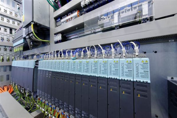
First, energy monitoring systems must be in place to effectively determine the current consumption. These can include, but are certainly not limited to, energy consumption displays, infeed/supply monitoring devices, power factor meters and more. Next, the proper calculation tools are needed to properly evaluate the life cycle costs of any investment. These tools can be as simple as a motor sizing chart or the software programs used to parameterize drives. However, a more formal mechatronics protocol may be beneficial to your operation. In this scenario, a thorough evaluation of both mechanical and electrical/electronic influences on your system, be it a machine or a process line, is conducted. The results can often open the eyes of machine designers, process engineers and system integrators alike. To realize the benefits this analysis the proper products and system solutions must be implemented.
This is where a competent supplier can be an effective partner for your operation. For example, the solution you need might involve a vector drive that utilizes an energy optimization function to enhance the efficiency of the motor during partial load operations. In a system with multiple motors, energy savings might be realized to a substantial degree by the use of a drive unit with a common DC bus. The designer can also select the most appropriate infeed solution for the machine, pump or process operation, given the particulars of performance and required output. This may include an appropriately sized infeed unit with regenerative capability, the ability to put unused or braking energy back on the incoming power line.
Some applications may allow the use of high efficiency standard induction motors and, in the process, realize a potential savings of 1-3%. The use of frequency converters (VFD) for speed control might raise this to an 8-10% savings. VFDs have myriad applications throughout industry on fans, pumps, blowers and compressors, as well as in wasted energy recovery on cyclical acc/dec and regeneration on lost braking energy applications.
Optimizing your entire system through mechatronic analysis of the machine or process design, can result in a potential savings of 15-20% by the avoidance of over dimensioning of motors, plus partial load optimization by means of energy-related flow control. This analysis may also point to the ability to use controlled energy infeed and recovery.
In order to determine the true efficiency of any drive system, it is necessary to demonstrate the amount of energy required by its power components and a corresponding examination of how the system uses energy. How different drive concepts used on the same system under identical power load must also be considered. This latter exercise might look into partial load efficiencies with various motor and drive combinations, straight comparisons betweens synchronous servo vs. asynchronous induction motors or direct drive vs. motor/gearbox combinations, drives with braking components vs. regenerative drive technology, as well as solutions with single vs. multi-drive, common DC bus solutions.
A corollary to this discussion should also include a review of potential hydraulic/pneumatic component change outs in certain applications where replacement with an integrated package of motion control and PLC technology might better resolve closed loop pressure control of axes, for example. Fewer components and their related power consumption can lead to overall system productivity improvements, as well as ongoing enhanced energy efficiencies. Reduced programming, diagnostic and commissioning times can also flow from such an approach, providing even more opportunities for overall machine or process improvements. Tracking the energy efficiency of such a system may seem problematic at first, but here again today’s sophisticated mechatronic and virtual production protocols can be utilized to validate the real-world performance characteristics of such designs, far in advance of their implementation.
As the emergence of new technologies has impacted many of the products used in energy-efficient systems, it is equally important to take a more holistic look at operational sequences and the overall integration scheme when designing, retrofitting or rebuilding for improved energy utilization. The results can be many, including precise process and power factor control for optimum energy use and significant cost savings, plus the collateral benefits of lower carbon footprints, reduced maintenance due to decreased mechanical stress and lower total cost of product quality derived from less mechanical wear and better production control.
Author: John Krasnokutsky
Email: john.krasnokutsky@siemens.com
Website: http://www.usa.siemens.com/motioncontrol
Siemens Industry, Inc.
5300 Triangle Parkway
Norcross, GA 30092
For an informative PowerPoint presentation or more information on this subject, call (800) 879-8079 ext. Marketing Communications or send an e-mail to: SiemensMTBUMarCom.industry@siemens.com.
Continue reading
ATLANTA — Siemens announced today the release of the new Simatic® CPU 317TF-2DP controller that combines motion control, safety and standard tasks in a single device. This device is the latest solution in its totally integrated automation portfolio that integrates and combines devices for the plant floor environment, further reducing footprints and improving overall efficiencies.
The Simatic CPU 317TF-2DP controller unites a series of important features that all go together in one device to reduce the wiring, coding and the implementation times. It also benefits users by saving space on the shop floor and reducing overall total cost of ownership.
Possible applications for the new device range from controlled single-axis positioning to complex, synchronized sequences of motion, such as geared synchronous motion, curve synchronization or print mark correction. The synchronous axes can be coupled to a virtual master or a real master. For safety-oriented applications, the controller fulfills the rigorous requirements of all the relevant standards, including EN 954-1 up to Cat. 4, IEC 62061 up to SIL 3 and EN ISO 13849-1 up to PL e.
For Siemens PLC users, the Step 7 option package S7-Technology is available to simplify engineering and commissioning. The Step 7 option package, supporting simultaneous processing of up to 64 technology objects, is available to meet engineering requirements for programming and commissioning of all functions. For specific fail-safe applications, the Step 7 option package Distributed Safety offers a set of pre-configured library blocks, including emergency stop, two-hand control, muting and door monitoring. No external safety hardware is required for costly safety precautions at the machine, saving valuable space in the control cabinet.
Centralized and distributed fail-safe I/O and fail-safe drives according to PROFIsafe, the fail-safe communication standard, can be connected to the Simatic CPU 317TF-2DP. The drive safety functions SBC, SLS, SSM, SOS, SS1, SS2 and STO according to PROFIsafe can be used in addition to the familiar safety functions.
PROFIsafe both enhances this controller’s capabilities and value while further simplifying commissioning. In particular, PROFIsafe requires less wiring than other controllers available in the market, making it quicker and easier to set up while reducing the risk of errors through the commissioning process.
For more information, visit www.usa.siemens.com/motioncontrol.
For specific product information and inquiries, call (800) 879-8079 ext. Marketing Communications or send an e-mail to: SiemensMTBUMarCom.industry@siemens.com.
Continue readingSinumerik MDynamics Milling Roadshow is coming to IMTS 2010.
If your company is looking for the way to more efficiently cut parts for aerospace, automotive or medical, one thing is certain — the demand for five-axis CNC machining has risen dramatically. And now there’s MDynamics: using one solid CAD/CAM/CNC process chain will get you to market faster than your five-axis competitors who will be lagging under a less integrated approach.
What is Sinumerik MDynamics?
“For users, it is extremely important to get from the blueprint to the finished part quickly, precisely and cost-effectively,” says John Meyer, marketing communications manager, Siemens Industry, Inc. “Sinumerik MDynamics combines our milling expertise together with our powerful Sinumerik CNC hardware platform, intelligent CNC functions, and our unique CAD/CAM/CNC process chain to form integrated technology packages for three- and five-axis milling.”
Seeing is believing.
According to Robert Scholz, international business development manager, Siemens Industry, Inc., Motion Control Business, “Together with leading machine tool OEMs, Siemens will demonstrate how users can benefit from accurate, high-speed machining and perfect workpiece surfaces. Every roadshow event will demonstrate part programming and simulation with NX CAM, followed by five-axis part manufacturing using MDynamics functions and Sinumerik CNC. With real applications for the automotive, aerospace and medical industry, we will prove to our customers that we are the perfect fit for every industry.”
From A-Z and everything in between, Siemens has you covered.
By providing a uniform and integrated system that ranges from programming directly at the CNC for simple parts, to a CAD/CAM system for complex workpieces, Siemens has the right solution for all CNC machining needs. With NX CAM, Siemens provides manufacturing engineers with an open and flexible 3D system that applies not only to the development of part models and drawings, but also to full NC programming and machining simulation. NX enables 3D and 2D construction in a full-, partial- and non-paramaterized form. The fully-integrated NX CAD/CAM system supports a complete part model to CNC program process and even offers 3D quality inspection programming in the same system. NX CAM provides optimized output for Siemens-controlled machines with additional programming commands and automated post-processor functions. During planning and into production, special focus is placed on the process related to the workpiece.
This process chain includes:
Product and process development using advanced CAD/CAM software
Part program generation for the most advanced machine tools
Optimized part program and post-processor output for maximum machining performance
Integrated and offline simulation for checking and optimization of manufacturing process on the PC
Optimized and highly-efficient manufacturing on the machine
See what Sinumerik MDynamics can do for your business!
Attend the Siemens Sinumerik MDynamics Milling Roadshow.
Roadshow schedule
20-minute demonstrations every day
during IMTS, September 13–18, 2010
12:30 p.m. — Milling for Medical
DMG/ Mori Seiki, booth S-8900
1:30 p.m. — Milling for Automotive
Grob Systems, booth S-9066
2:30 p.m. — Milling for Aerospace
MAG, booth S-8519
www.usa.siemens.com/cncroadshow
Continue reading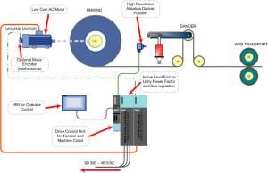
by William Gilbert, Industry Business Development Manager, Converting and Cranes, Motion Control Solutions
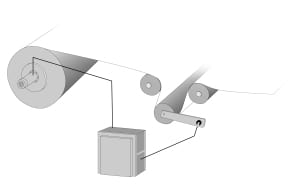
During the operation of any converting machine, whether for film, foil, wire, paper or board, plus most large printing presses, rolls of materials are handled by unwinds, often still driven by pneumatically operated braking systems. The traditional tension control system for an unwind stand is a simple mechanical brake. In principal, the unwind brake mechanically operates much like the braking system on your car, with a disk, caliper and pads, but is controlled by a tension sensor linked to a setpoint controller. As the roll unwinds, the tension is maintained by the brake for smooth passage of the material through the dies or rollers, resulting in better package alignment, less wrinkling, better print registration, even more consistent wire dimensioning and other production positives. These mechanical brake unwinds are effective in controlling the tension, but have inherent problems of heat and power loss, plus mechanical wear and constant maintenance needs, substantially impacting machine uptime.
The typical mechanical brake is pneumatically controlled and may utilize several sets of friction pads to control the web tension as the roll dimension decreases. Plus, a reasonable pressure range in many applications might be from 15-90psi or a 6:1 drop, a range significantly less than the core to full roll ratio for most jobs, an obvious inefficiency in operation.
To affect good tension control on the brake, these friction pad sets need to be manually changed in an out of the brake assembly, depending on the desired operating tension and the roll diameter changes involved. Often, the adjustments are several per roll during this manual changeover. Because the mechanical brake creates the unwind tension through friction, it generates substantial heat and often requires a separately powered fan for cooling to operate effectively. This friction also means the pads are subject to rapid wear, requiring frequent and time-consuming changes or maintenance checks.
For almost a decade now, this old technology has been gradually replaced, though usually in the lower power ranges, by newer precision technology, involving AC motors, drives and electronic loadcells. On converting lines today, a further leap forward is being made with the onset of 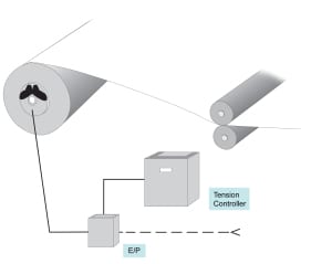
With such technology, the operating principle is as follows.
Since the unwind application is regenerative (regen) in nature, a driven unwind needs to return the energy that the mechanical the brake produced as heat back to the AC line. In the past, regen DC drives have been successfully applied as driven unwinds, but DC drive systems are no longer common and even during their prime were very costly. Early in the AC drive technology for these applications, the drives did not have the capability to regenerate the power back to the AC line and, when applied as unwind brakes, required regen resistors to dissipate the tension energy. This was wasteful and costly.
Today’s AC drive systems now have the technology to regenerate the energy back to the AC line just as the DC drive did, but with added benefits to the user and machine designer alike. Sending the tension energy back to the line means power that once was wasted can now be retained, instead of the system producing heat and worn parts. When the drive is equipped with active front end technology, it will return the previously wasted energy with near unity power factors, something not possible for any DC drive system.
Even an open loop AC drive motor combination offers a tension control range far beyond the limits of a pneumatic braking system. Synchronous AC motors can offer precision open loop torque control without a tension sensor, thereby saving further cost and inventory. Today’s highly accurate tension control systems can be designed with high resolution (sin/cos) feedback encoders on both the unwind motor and dancer position feedback. Additionally, in more advanced active front end designs, the regen capability of the drive can actually assist in the increase of stopping times and tension control regulation, owing to the four quadrant control, i.e., the motor can sink or supply current to the motor in both directions.
Beyond the obvious cost savings of pad replacements on mechanical braking systems, AC motors are virtually maintenance free by comparison to DC motors, as AC motors have no brushes, do not require controller contactors to reverse direction of motor rotation or have commutators. Fewer moving parts invariably means less motor maintenance, for additional cost and time savings.
In the most advanced systems, common DC bus regulation, energy-monitoring devices for near unity power and, through the use of mechatronic services often provided by the manufacturers, “turn off” parameters in vector drives are possible. Mechatronic services can also be utilized for the proper tuning of these drives onsite or during machine build. For designers, such services further assist in the proper sizing of motors, based on the mechanical and electrical forces generated by machine operation or computerized simulation of it.
This combination of improved operation, reduced maintenance, motor power savings and conservation of nearly all energy within the system make AC regen drives with active front end technology a decided advantage for machine designers and end users of converting, packaging, printing, wireforming and other roll-fed machinery, where driven unwinds can be implemented.
For more information on regenerative drive motors and systems, please contact:
Siemens Industry, Inc. Drive Technologies — Motion Control
390 Kent Avenue Elk Grove Village, IL 60007 Phone: 847-640-1595 Fax: 847-437-0784 Web: www.usa.siemens.com/motioncontrol Email: SiemensMTBUMarCom.sea@siemens.com
Attention: John Meyer, Manager, Marketing Communications
Editor Note: Siemens will make the author as well as various other product and market specialists available to you for interviews on the many aspects of regenerative drive motors detailed in this article, as they apply to the particular nature of your audience. Please contact the agency to arrange. Thanks!
PR agency contact: Tim Daro Bernard & Company 847-934-4500 tdaro@bernardandcompany.com
Continue reading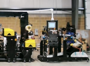
Joe Drilling has a pride in his company that’s classic American entrepreneur. After years at a leading label machine builder, he founded Drilling Technical Services (DTS) in Milford, Ohio, a virtual engineering company specializing in the mechanical, electrical and process engineering of mid-width and narrow web printing, drying, converting, RFID and digital print equipment. DTS has a particular emphasis on web transportation, die-cutting and laminating solutions. As the installed base grew and responding to current market conditions, Joe founded a second company, Pre-Owned Press & Parts Solution LLC (POPPS), also in Milford, specializing in the evaluation, reconfiguration, remanufacturing, sale, commissioning and servicing of pre-owned presses. Another vital component of the business models at both DTS and POPPS is the engineering of energy recovery systems for containment of utility costs, an ongoing challenge in the printing industry.
The two companies primarily serve the needs of the flexible packaging, folding carton, tag and label, health and beauty, wine and beer, plus other label segments.
During a recent project for one global leader in label and filmic product solutions, DTS was commissioned to develop a mid-width web roll-to-roll die cutter with various unique substrate manipulation functions. The substrate’s physical parameters, especially the desire to reduce material thickness, represented particular challenges to the DTS team.
DTS utilized its “QC Mod Cut Series” modular web transport system and quick change die cassette technology as the design platform.
Every aspect of the work was to be done to the customer’s strict system specifications for equipment criteria, including die cutting accuracy, line speed accuracy, tension control and wound roll precision. These process functions were to be controlled by the machine’s Human Machine 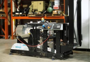
Based on previous experience with Siemens, the DTS engineering team looked to integrate electronic line shafting and process control functions that could be achieved with standard component architecture. Having a local and experienced distributor of Siemens components, Richard Equipment Company (RECO) in Cincinnati, the investigation into a process solution began. As Joe Drilling further noted, “The worldwide support of Siemens was an additional factor in our decision and really gave us that comfort zone in selecting them for this project. Our customer is itself a world player and so we felt confident in Siemens’ ability to provide components and service, wherever needed.”
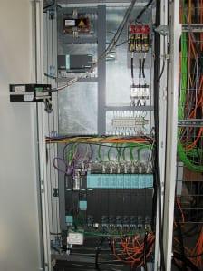
To achieve the desired accuracies in every machine function, DTS utilized the Siemens Simotion D435 motion controller, a compact, drive-based platform that incorporates motion control, logic control and drive control in a single hardware unit for drive mounting. In this manner, the drive became the control for the entire machine’s functionality. Feeding off this platform are the multi-axis control drives of the Siemens Sinamics family, as well as Simatic I/O components and runtime software, plus the related HMI hardware, as supplied by RECO.
Components were selected by the DTS engineers using the unique Siemens Converting Toolbox, a suite of product specifications and application software that allows an engineer the flexibility to customize portions of a machine build, then recall and reuse them or make modifications for subsequent builds. The reduction in subsequent machine design engineering time, according to Joe Drilling, reached approximately 80 percent on the second machine and he anticipates a repeat of that scenario, every time.
These factors were found most satisfying for DTS and especially their customer, who had previously used a vendor for machine upgrades who typically took months, even years, to research, develop and implement design changes in the customer’s machine lines, according to Drilling. “With our more simplified layout of components and the flexibility we enjoyed with the Converting Toolbox, the learning curve shortened tremendously. Product and Matrix winder modules were able to be configured to allow the diverse web tension ranges and accuracy required. And, most of all, the shaftless drive system we implemented allowed our web transport roll design on the individual machine sections to become much easier, faster and completely repeatable.” The end result is very accurate web control and re registration capability.
Siemens system training and project development took place on-site at DTS.
Other recent projects accomplished by DTS engineers include an air-to-air heat exchanger for dryer efficiency, a dryer system upgrade for water-based inks, a unique accumulator stacker specially designed for thin substrate processing, a near-zero defect RFID system and various anilox system upgrades to integrate more advanced motion control technology. The company also performs considerable process layout and process improvement consulting to its customers throughout the industry.
For more information on this story, please contact:
DRILLING TECHNICAL SERVICES INC.
6062 Kells Lane
Milford, OH 45150
Phone: 513-831-2952
Fax: 513-831-4825
Web: www.drillingtechservices.com
Email: jdrilling@drillingtechservices.com
Attention: Joe Drilling, President
Or
SIEMENS INDUSTRY, INC.
Drive Technologies — Motion Control
390 Kent Avenue
Elk Grove Village, IL 60007
Phone: 847-640-1595 Fax: 847-437-0784
Web: www.usa.siemens.com/motioncontrol
Email: SiemensMTBUMarCom.industry@siemens.com
Attention: John Meyer, Manager, Marketing Communications
—
Drilling Technical Services Inc. in Milford, Ohio is machine builder specializing in the mid-width and narrow web press market. Its sister company, Pre-Owned Press & Parts Solutions, offers full reconfiguration engineering and remanufacturing services, plus full installation and commissioning on pre-owned presses.
Through the use of the Siemens Converting Toolbox and Simotion selection of drive/control technologies, all the motion control drive-based components and logic software were selected from a suite of available options. A reduction of over 80 percent in engineering time has been reported by the machine builder.
Continue reading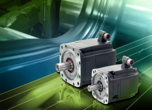
These self-cooled 1FK7-HI servomotors provide stall torque in the 3 Nm to 20 Nm range and are offered in IP64 or IP65 with IP67 flange degree of protection, with selectable options for plain or keyed shaft, holding brake, 22-bit incremental or absolute encoders, as well as 18 color options.
A mechanical decoupler between the motor and encoder shaft protects the encoder from mechanical vibrations, providing a long service life. In cases where the encoder needs to be exchanged, the device automatically aligns the encoder signal to the rotor pole position, enabling feedbacks to be changed in the field in less than five minutes.
These new Siemens 1FK7-HI servomotors also feature the unique Drive-Cliq® serial bus and electronic nameplate recognition, allowing virtual plug-n-play operation when paired to the Sinamics® S drive platform. All servomotors in this new line are also configured to interface with Siemens Sinumerik® CNC technology for machine tool applications and the motion controller Simotion® for general motion control use.
Selecting the proper motor to suit the application is facilitated by the Siemens Sizer® toolbox and compatible 3D CAD model-generating CAD-Creator package. For more information, visit www.usa.siemens.com/motioncontrol.
For specific product information and inquiries, call (800) 879-8079 ext. Marketing Communications or send an e-mail to: SiemensMTBUMarCom.industry@siemens.com.
Continue reading
by Harald Poesch, Product Marketing Manager, Servomotors
Today’s machine designer must evaluate more factors than ever in approaching a new project. Likewise, the integrator and retrofit engineer has expanded options, not only as a result of new technologies, but also because of critical areas of focus such as reduced 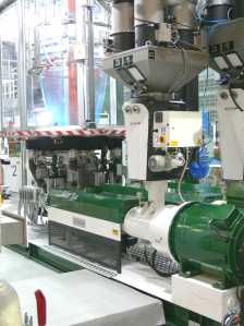
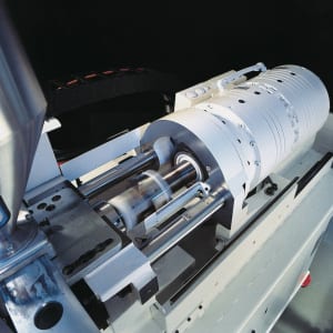
In the realm of motion control, one type of motor with a relatively short history has made significant advancements that necessitate a new look at its potential in many application areas. These applications range from machine tool rotary tables to various packaging, printing, converting, extruding, papermaking, plastic film and materials handling machinery, anywhere direction must be reversed with a very high degree of accuracy, no backlash (hysteresis) and the maintaining of motion control, contrasting the necessary decoupling of a conventional motor and gearbox.
Enter the often-overlooked permanent magnet, synchronous torque motor.

Two popular varieties of torque motors exist today. They are the complete torque motor, requiring only direct flange-mounting to the machine and connection of the rotor to the machine shaft, and the built-in torque motor, where the stator and rotor are supplied as individual components that are directly integrated into the machine mechanics.
Complete torque motors are often found on extruder main drives, feed heads on injection molding machines, roller drives on papermaking machines, wire drawing devices, textile machine web stretching and winders/cross cutters on packaging equipment.
Built-in torque motors are typically used on machine tool rotary tables, swivel axes, dynamic tool turrets and turning spindles, as well as printing press cylinders, chill rolls in cast film and foil stretching machines, indexing tables in metalforming presses and all other types of 
Both types of torque motors feature a hollow shaft, which allows media or mechanical components to be guided through the rotor cavity.
Torque motors are multiple pair pole synchronous motors, similar in operation to rotary synchronous servo motors. The rotor is equipped with permanent magnets, while the stator contains the motor windings. The high number of pole pairs leads to a design generating high maximum torque at low speeds. In the past, since eddy current losses increase with the number of pole pairs and the running speed of the motor, torque motors were considered applicable only at relatively low speeds. New water-cooled designs have countered this principle, allowing a high power density. Today’s torque motors can accommodate speeds of 1000 rpm or higher.
As a result of these higher pole pair designs and because many mechanical power transmission components that generate backlash, heat, friction and noise are eliminated, torque motors offer these benefits to designers:
While higher in cost than geared motors, it is currently estimated that torque motors offer the designer a payback of three to four years in energy savings alone, which does not include the immediate increased performance and upfront cost savings, both in installation and maintenance. Obvious vendor reduction and inventory advantages are also realized through the use of these motors.
On a typical multi-layer blown film line, for example, the use of torque motors can reduce the footprint of the extrusion section by half and the consumed production space decreases accordingly, leading to an increase in production rates per square foot.
Torque motors were also long thought to be susceptible to chemical and other ambient atmospheric contamination, but new designs have been adapted to withstand corrosive atmospheres such as a paper mill dry hood and, being water-cooled, are performing satisfactorily in many harsh environments without heat damage. Enclosures are available up to an IP54 rating with overload capability up to 2.5 times the rated torque.
Torque motors reduce mechanical efficiency losses to an absolute minimum because they eliminate mechanical transmission in the drive train. Compared to geared motor solutions, the efficiency gain is typically in the range of 10 percent, while the gain is closer to 70 percent when hydraulic motors are replaced in applications such as injection molding machines. Further, due to the direct and constant control of the load shaft on torque motors, with no backlash or decoupling occurring, a significantly higher precision in motion is achieved, which is not possible in a geared or belt-driven solution.
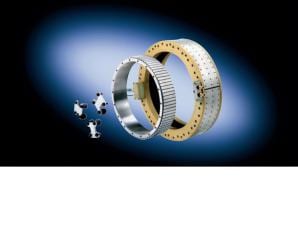
Other features on today’s torque motors that make them more appealing for the machine designer include:
The emerging science of mechatronics is also critical for direct drives such as torque and linear motors in the integration process because the electronic machine control protocols are so crucial in monitoring and executing the electromechanical motions. A keen knowledge of three 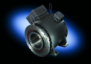
Additionally, through various advanced computerized simulation techniques, mechatronic performance can be validated and troubleshooting on the design can be accomplished before the first machine is ever built. Even in the field, before and after a retrofit or rebuild, the mechatronic services currently available can be used for product application determination, full performance analysis and controls compatibility. While the performance of a new motor or drive might be deemed satisfactory by mechatronic analysis, other mechanical, electrical or electronic components might be found lacking. It is precisely this comprehensive, integrated approach that is fast earning mechatronics its place in the overall scheme of machine development and utilization.
In conclusion, with today’s emphasis on cost containment, energy efficiency and higher productivity on every type of machine design, it is imperative that all viable options be explored. In designing the drive train on many machines, the advantages of torque motors described in this paper will have a positive impact on the overall project results. Torque motors can offer great flexibility in design, retrofit and rebuild applications, plus they have expanded capabilities that lobby for their implementation on more types of machines.
For further information on torque motors, please contact:
SIEMENS INDUSTRY, INC.
Drive Technologies — Motion Control
390 Kent Avenue
Elk Grove Village, IL 60007
Phone: 847-640-1595 Fax: 847-437-0784
Web: www.usa.siemens.com/motioncontrol
Email: SiemensMTBUMarCom.industry@siemens.com
Attention: John Meyer, Manager, Marketing Communications
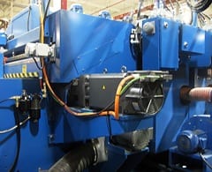
Fred Harrison, president of Hycorr Machine Corporation, a Kalamazoo, Mich. builder of corrugated boxmaking machinery, has always believed in being first. That competitive and can-do spirit meets every visitor to his company’s website, where a number of Hycorr first’s are listed. The company was the first U.S. rotary die-cutter to introduce an integrated stacker, the first U.S. builder to introduce the reverse angle doctor blade on rotary die-cutters and the first builder in the world to offer an automatic cutting-anvil speed compensator, Auto-CompTM, which was later joined by Hycorr inventions of a quick-change anilox roll system and modular dwell section with inter-station dryers. All these innovations to the industry were achieved in the first 15 years of operation for this company, founded by Fred Harrison in 1985.
Never one to rest on his laurels, Harrison recently put his engineering team on the task of improving the overall controls package on the company’s line of rotary die-cutters. In particular, the servo system and total controls package needed upgrading with newer technology. The previous technology functioned properly and to a satisfactory degree to keep the company competitive in the paperboard container industry, but Hycorr engineers were seeking increased cost containment and a reduced footprint, with no loss in performance on their machines.
After considerable research, and based on the direct experience of a recently hired engineer, Hycorr began its investigation of a totally new system, one that would not only reduce servo drive system and related energy costs, but also integrate both the programmable logic controller (PLC) and human-machine interface (HMI) functions.
Hycorr’s electrical engineer, Mike Walter explains, “We have been building servo driven rotary die-cutters for over 10 years. We wanted to look at a new system for a series of machines that were being built for new customers. After the first price pass, we knew we needed to continue our talks with Siemens.” The package under consideration included servo motors, Sinamics® S120 servo drives, and a Simotion® D motion controller with PLC functionality. Walter continues, “At first, we were only considering this new system for the motion platform. We needed a servo system that would eliminate some gears and maintain the tight tolerances our customers expected for printing and diecutting. We really needed a system with built-in rotary motion functionality.”
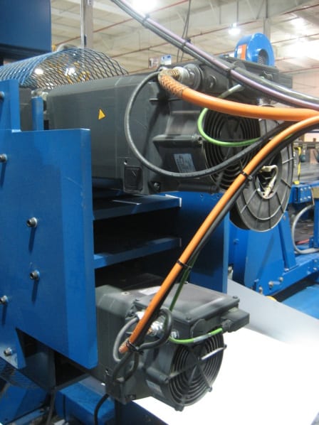
In the proposed implementation of the new solution, each technology (motion, PLC and HMI) had built-in connectivity to the others, making assembly time another area for major savings for this machine manufacturer. Overall, the savings for Hycorr was calculated to be approximately 50 percent,
Capping the decision to make the switch to the Siemens solution was a footprint reduction of 30 percent in control cabinet space. As Walter simply puts it, “The components were smaller. With the combination of the active interface module and active line module, we eliminated the need for line reactors or line filters, thereby saving space, plus mounting and hardwiring time.” Complementing these savings, the Siemens servomotors specified for comparable performance levels were considerably smaller and less expensive to operate than the previous units used.
Working under a tight deadline, the first rotary die-cutter was built and commissioned onsite by Hycorr and Siemens at the end user’s plant. Shortly thereafter, the second machine, needed by another Hycorr customer, was built on a production schedule that Fred Harrison would deem another first for the company in its speed. This improvement in engineering, production and assembly time resulted from the Simotion Shaftless Standard provided at no cost by Siemens to its customers. This Shaftless Standard enabled Hycorr engineers to do much more modular implementation of components plus the interfaces of the overall motion system to the controls architecture. By this process, Hycorr saved approximately 80 percent of its engineering time on the machine build. The entire engineering file for the first machine was loaded from a single compact flash drive and, with minimal debugging, the engineering on the second machine was completed quickly. This demonstrated the serial machine benefits of Simotion, according to Mike Walter.
Components used on the machine builds at Hycorr included Siemens Sinamics S120 drives, Simotion D425 motion controller, 1PH7 servomotors and Simatic® S7 PLC for simple Windows-based operator interface. As part of the Shaftless Standard package, Hycorr is able to make custom modifications to the various options offered on its rotary die cutters, without extensive engineering time.
Fred Harrison concludes, “Hycorr will continue to strive to be first on the market with many innovations, always maintaining the highest quality standards of machine performance. No customer will ever be a trial case for us. We deliver productivity to our customers’ bottom line because we’ve invested in maximizing our own.”
For more information on this story, please contact:
Hycorr Machine Corporation
5801 East Kilgore Road
Kalamazoo, MI 49048
Phone: 269-381-5905
Fax: 269-381-5914
Web: www.hycorr.com
Email: info@hycorr.com
Attention: Fred Harrison, President or Mike Walter, Electrical Engineer
Or
SIEMENS INDUSTRY, INC.
Drive Technologies — Motion Control
390 Kent Avenue
Elk Grove Village, IL 60007
Phone: 847-640-1595 Fax: 847-437-0784
Web: www.usa.siemens.com/motioncontrol
Email: SiemensMTBUMarCom.industry@siemens.com
Attention: John Meyer, Manager, Marketing Communications
The key is a process, not a product, with many factors contributing to energy efficiency.
What is the key to more energy efficient motion control?
While it is valid to state that energy efficiency is defined as the same level of production being achieved at an overall lower energy cost, it is equally important for today’s machine builders and automation engineers alike to remember than an energy-efficient system can actually translate into higher productivity. This is achievable through a comprehensive approach to energy management. Energy management is a process, rather than a product or series of products installed on a machine, or inline, to achieve a basic energy saving of kW hour consumption.
What are the essential elements and basis of the process?
First, energy monitoring systems must be in place to effectively determine the current consumption. These can include, but are certainly not limited to, energy consumption displays, infeed/supply monitoring devices, power factor meters and more. Next, the proper calculation tools are needed to properly evaluate the life cycle costs of any investment. These tools can be as simple as a motor sizing chart or the software programs used to parameterize drives. However, a more formal mechatronics protocol may be beneficial. In this scenario, a thorough evaluation of both mechanical and electrical/electronic influences on a system, machine or process line is conducted. The results can often open the eyes of machine designers, process engineers and system integrators alike.
What is the general approach to a mechatronics analysis?
This is where a competent supplier can be an effective partner. For example, a solution might involve a vector drive that utilizes an energy optimization function to enhance the efficiency of the motor during partial load operations. In a system with multiple motors, energy savings might be realized to a substantial degree by the use of a drive unit with a common DC bus. The designer can also select the most appropriate infeed solution for the machine, pump or process operation, given the particulars of performance and required output. This may include an appropriately sized infeed unit with regenerative capability, the ability to put unused or braking energy back on the incoming power line.
Some applications may allow the use of high efficiency standard induction motors and, in the process, realize a potential savings of 1-3%. The use of frequency converters (VFD) for speed control might raise this to an 8-10% savings.
Optimizing an entire system through mechatronic analysis of the machine or process design, can result in a potential savings of 15-20% by the avoidance of over dimensioning of motors, plus partial load optimization by means of energy-related flow control. This analysis may also point to the ability to use controlled energy infeed and recovery.
What technologies should be evaluated?
A corollary to this discussion should also include a review of potential hydraulic and pneumatic component change outs in certain applications where replacement with an integrated package of motion control and PLC technology might better resolve closed loop pressure control of axes, for example. Fewer components and their related power consumption can lead to overall system productivity improvements, as well as ongoing enhanced energy efficiencies.
As the emergence of new technologies has impacted many of the products used in energy-efficient systems, it is equally important to take a more holistic look at operational sequences and the overall integration scheme when designing, retrofitting or rebuilding for improved energy utilization.
Michael Perlman is the Marketing Programs Manager for the Motion Control business of Siemens Industry, Inc.
For specific product information and inquiries, call (800) 879-8079 ext. Marketing Communications or send an e-mail to: SiemensMTBUMarCom.industry@siemens.com.
Continue readingComplete Set of Application-Ready “Tools” for Converting Applications
ATLANTA — Siemens Industry, Inc. announced today the introduction of the Converting Toolbox, a set of standardized automation tools for the integration of various machine components that previously had to be performed individually. It simplifies web processing applications and offers greater flexibility for machine designers and builders of paper, film, foil and other converting machinery. It is completely scalable and is provided at no cost to qualified machine designers, builders and integrators.
The Converting Toolbox enables machine builders to achieve considerably faster time to market by reducing the time required for engineering, programming, commissioning and documentation, as much as 80 percent in some cases. It offers modular open functions, for items such as:
The Converting Toolbox components take the form of pre-programmed functions. Sample applications demonstrate how each function can be efficiently and effectively implemented into a machine design. Such sample applications are ready-to-use after only minor modifications and include basic HMI functionality. This enables the machine function to be tested and optimized in a very short time frame.
When a functionality module needs to be modified, extended or changed, the Converting Toolbox’s completely open source code provides a wide and solid basis from which even the most specialized functions can be implemented quickly and easily.
Simotion®, the Siemens motion control system, is ideally suited as an operating platform for the Converting Toolbox because applications can be operated directly on an intelligent drive, very compactly and without need of an additional PLC. Simotion offers drive, controller and PC-based topologies. The Converting Toolbox also includes drives-based solutions using Siemens Sinamics® Drive Control Chart (DCC) graphical programming language.
For specific product information and inquiries, call (800) 879-8079 ext. Marketing Communications or send an e-mail to: SiemensMTBUMarCom.industry@siemens.com.
Continue reading