
Contact us today:
(847) 934-4500
tdaro@bernardandcompany.com
Contact us today:
(847) 934-4500
tdaro@bernardandcompany.com
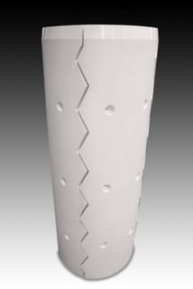
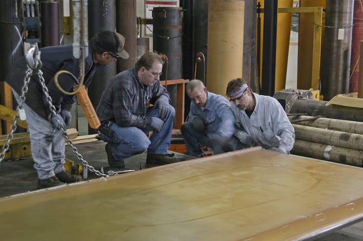
Kastalon engineers match assorted textured surfaces and material hardnesses to the application.
Kastalon offers mills and processors highly engineered polyurethane mandrel sleeves, filler plates and filler rings with material hardness and surface options to match customer needs, protecting coils from damage
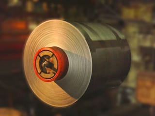
Kastalon brings 50 years experience in coil processing to the task of engineering a new offering of application-specific, proprietary formulated polyurethane mandrel sleeves, filler rings and filler plates. These products are designed to adapt the mandrel to handle coils with larger ID’s and addresses the problems of damage from creasing, scratching and marring at mills, service centers, toll processors and fabricators alike. Such damage is expensive for any coil handling operation, especially when the metal is prepainted or must maintain optimum cosmetic surface integrity. By the use of Kastalon mandrel sleeves, filler rings or filler plates on the uncoiler or recoiler, the inside wraps on coils are protected from metal to metal contact. More finished material is produced or usable, as a result.
Mandrel sleeves are custom designed with engineered surface hardnesses and grooved or smooth finishes, depending on the particular application. Full sleeves are usually recommended for the recoilers, while filler rings and filler plates are more often utilized for uncoilers.

The design process begins at the company website, where a detailed needs-assessment questionnaire can be completed, followed by a discussion with Kastalon engineering to formulate the proper chemistry, surface and material hardness for the application.
In use, the proprietary chemistry of the Kastalon Polyurethane material withstands the stress caused by the weight of the coil, then reforms when the mandrel is collapsed back to the rest position, owing to the inherent memory of the Kastalon engineered material. With other materials now on the market, sleeves will often sag due to memory loss and the resulting gap can cause significant coil damage. Correspondingly, additional labor and line downtime result from this condition, as realignment of the coil, sleeve and mandrel is needed. Through the true and precise sizing of the mandrel sleeve, combined with the proper material hardness and surface texturing, a Kastalon sleeve can last up to 10 times longer than rubber, fiber or even other commodity type polyurethane products, according to company research, available on request.
Mandrel sleeves, filler rings and filler plates allow coil processing to be accomplished more efficiently, whether on uncoil or recoil reels, at mills, service centers, toll processors and fabricators.
Kastalon mandrel sleeves are non-marring, cut-resistant, abrasion-resistant and offered for friction fit, requiring a separate “keeper”, or bolt-on installation. Company engineers consult customers on the amount of lubricant, cleaning solution or other coating chemistries present in the process, as this will determine the particular formulation selected. Furthermore, Kastalon offers these mandrel sleeves in a wide variety of grooved or soft surface finishes to meet the specific tension and pressure requirements of a processor’s uncoil/recoil apparatus. Special dual-durometer sleeves are also available for mills and processors where “head-in” damage is often encountered.

Kastalon engineers match assorted textured surfaces and material hardnesses to the application.
For most uncoilers, Kastalon filler rings or filler plates can provide the optimum performance for the tension, pressure and metal contact requirements typically present.
The design process for Kastalon mandrel sleeves can begin with a visit to the company’s website, www.kastalon.com, for completion of a needs assessment questionnaire. Detailed information is gathered on this form, allowing the Kastalon engineers to calculate the best sleeve design and chemical composition to suit the job.
For more information on this product, please contact:
KASTALON, INC.
4100 W. 124th Place
Alsip, IL 60803
Phone: 708-389-2210
Fax: 708-389-0432
Web: www.kastalon.com
Email: sales@kastalon.com
Attention: Marty Pokorney
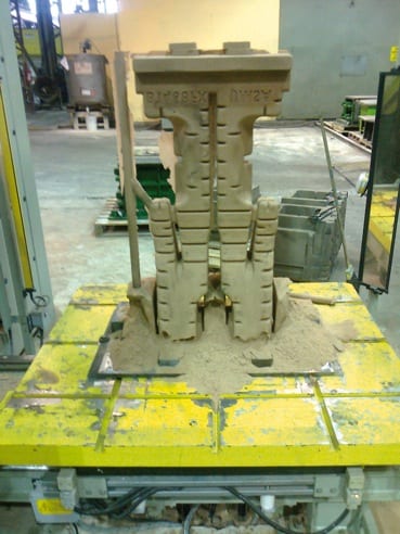
Figure 1. First Core Blowing Test. The bottom of the core collapsed due to a lack of strength.
Brazilian steel giant Usiminas recently introduced the new foundry core making simulation software MAGMASOFT® as part of their strategy to establish robust designs and processes for their core production line. The first project on which this software was utilized was already in progress at that time.
The main goal was to optimize the process conditions for the existing tooling layout. This core, called the thin waist core, represents some of the biggest challenges for Usiminas core production: its length (920 mm), substantial changes in the sand flow direction during blowing, the need to fill certain parts of the core through counter-flow and big variations in the cross section within the core.
First trials showed problems with the process, which led to a complete collapse of the lower part of the core. The core blowing and curing steps for the PU coldbox process were analyzed, making it possible to draw preliminary conclusions regarding the existing defects.
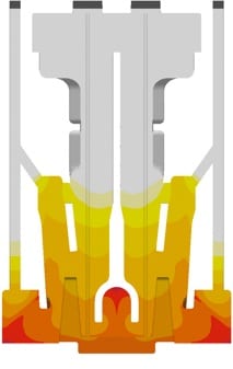
Figure 2. Curing Gas Concentration. The curing gas does not penetrate into the core to the same extent everywhere.
The lack of core strength was related to a poor curing process. The first simulation (Figure 2) already showed that the problematic regions experienced only very low curing gas concentrations during gassing, which was the root cause for the failure.
On the production line, various process conditions such as the curing and purging times and gassing pressure were changed. These attempts provided better results (Figure 3). However, a perfect core could still not be produced. The further analysis with MAGMASOFT® focused on the evaluation of the local concentration of adsorbed curing gas, as it shows the regions where the catalyzing gassing agent cannot activate the chemical reaction. This result clearly demonstrated that only a very small quantity of catalyst was available for accelerating curing in the defect regions (Figure 3).
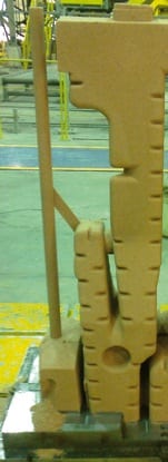
Figure 3. Core Blown with new parameters in comparison with the local concentration of adsorbed curing gas. The problematic area corresponds exactly with low concentrations in the simulation.
Evaluating simulated curves for the gas mass flow through the vents made it clear that the catalyzing gas was not reaching the critical area. The open venting cross section of the top and central vents was allowing the gas to escape before it reached the bottom of the core.
Instead of making costly modifications to the core box, Usiminas determined that a possible – and simple – solution was to close some vents in the top and center regions, in order to increase the gas concentration in the bottom. However, it was clear that these changes obviously would also influence the core blowing step.
The optimization led to a considerable increase of the curing gas concentration in the lower regions of the core (~36%) (Figure 4). Also, the amount of adsorbed curing gas increased in comparison to the original project. Applying these modifications, Usiminas produced another core, which did not show any gassing defects. Since the venting area was reduced, some filling defects were present, as expected.
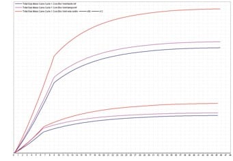
Figure 4. Total gas mass flow through the lower vents. The change in mass flow becomes clear. Removing some of the upper and middle vents resulted in a 36% increase in the gas escaping through the lower vents.
Having solved the curing related defects, a further core blowing analysis was carried out. The simulation results showed a very good match between the real defects and areas of low packing density. The flow animation also showed that the problems occurred because these areas had to be filled by a counter flow of the sand (Figure 5).
Another characteristic of the defects was that they all occurred next to the parting line of the core box. Some of the defects showed a smooth surface, indicating that the sand had been removed by a strong air flow. The core blowing simulation results supported the Usiminas conclusion that an improper sealing of the tool was the root cause for these defects. Air could escape with high speed through the parting lines, resulting in the defect formation.
This hypothesis was tested using a silicone rubber band to obtain an improved sealing of the relevant areas of the tool. With this modification, a new core was produced which was absolutely free of any defects.
About software for casting process simulation
Casting process simulation software considers the complete casting process including mold filling, solidification and cooling, and also provides the quantitative prediction of mechanical properties, thermally induced casting stresses and the distortion of cast components. Simulation accurately describes a cast component’s quality upfront before production starts, thus the casting layout can be designed with respect to the required component properties. This results in a reduction in pre-production sampling, but also the precise layout of the complete casting system leads to energy, material and tooling savings for the foundry.
The range of application of MAGMA solutions comprises all cast alloys, from cast iron to aluminum sand casting, permanent mold and die casting up to large steel castings. The software supports the user in component design, the determination of melting practice and casting methodology through to mold making, heat treatment and finishing. This saves costs consequently along the entire casting manufacturing line.
During the last 10 years, the use of casting process simulation has become a valuable business asset for many foundries worldwide. MAGMA5 constantly expands the capabilities of casting process simulation and will further accelerate the acceptance of this technology, in the future.
About Usiminas
With 50 years of operation, Usiminas is the leader in the Brazilian flat steel market and one of the largest steel companies in Latin America. It has a nominal capacity of 9.5 million tons of steel per year. Usiminas Mecânica is a leading provider of capital goods and services to the steel, railway, mining, automotive, energy, petrochemical, marine and infrastructure industries in Brazil. With recent substantial investments, the foundry of Usiminas Mecânica has become one of the largest manufacturers of both small and large steel castings in the country. The yearly production capacity is 30,000 tons, representing about 10% of the projected production in Brazil.
About MAGMA
MAGMA offers comprehensive solutions to the metal casting industry, casting buyers and casting designers worldwide. The MAGMA product and service portfolio includes the powerful modular simulation software MAGMASOFT®,with the newest release MAGMA5, as well as engineering services for casting design and optimization.
Today, MAGMASOFT® is used throughout the metal casting industry, especially for the optimization of cast components in automotive and heavy industry applications.
MAGMA Giessereitechnologie GmbH was founded in 1988 and is headquartered in Aachen, Germany. A global presence and support are guaranteed by offices and subsidiaries in the USA, Singapore, Brazil, Korea, Turkey, India and China. Additionally, more than 30 qualified partners represent MAGMA around the world.
For more information on this release, please contact:
Christof Heisser
President
MAGMA Foundry Technologies, Inc.
10 N. Martingale Road, Suite 425
Schaumburg, IL 60173
Phone: 847-969-1001 ext. 225
Email: cheisser@magmasoft.com
Web: www.magmasoft.com
Advanced Machine & Engineering (AME) provides solutions to run 56 different block sizes at Rockford-area machine shop
In its production of various cylinder and related products for hundreds of customers, TRD Manufacturing, Inc. of Machesney Park, Illinois (near Rockford), a division of Bimba, one of the leaders in actuation devices, was challenged by an ever-increasing variety of sizes, styles and materials in their workpiece blocks. As VP of Operations Kerry Reinhardt explains, “TRD is a fast-paced manufacturer but very dedicated to high quality and fast turnaround on deliveries. We have an established reputation as a solution provider to the fluid power industry.” The company sells through distribution with its end users found in the general manufacturing, automation integration, mining, forestry, medical, food and various mill industries. TRD products are regularly specified as OEM components, plus the company serves the huge MRO marketplace.
To meet the demand for products in an ever-expanding line, complicated by the just-in-time delivery schedules often encountered, as Manufacturing Manager Tom Jensen notes, “TRD was seeking a partner who could develop fixturing to fit our manufacturing business model of quick set-up and the flexibility to run small or large batches of product from a multitude of block sizes.”
TRD turned to a local supplier of various machine tool components, Advanced Machine & Engineering (AME) in Rockford, Illinois. The head of the AME workholding group, Alvin Goellner, observes, “After a few discussions and visits to each other’s plants, we knew TRD would benefit most from our Triag line of modular workholding devices.”
Tom Jensen concurs. “We knew AME had a reputation for building top quality fixturing. Their in-house manufacturing capabilities were very impressive and we knew they could handle a project of this size, based on the other customers they serve and the fact that they are just across town from us, which made it easier to work through the preliminary discussions, quoting and final product delivery.” The horizontal machining center (HMC) used for this particular application at TRD is an Enshu GE480H, with 30” x 30” x 30” travel and a 180-position toolchanger, expandable to 240-position. Workpieces are mounted and handled on a Fastems 10-station pallet changer. Currently, the block sizes run at TRD are 56 in number and run in sizes from 1” x 2” x 2” to 3” x 9-1/2” x 14”. Weights range up to 114 lbs. Final part varieties produced on the machine number over 450, made from 1018 steel and 303 stainless. Lot sizes vary from one-offs to 500, but generally run between 25-50 on average. This machining center set-up runs two shifts per day, with the expectation of running 24/7 during peak demand periods.
The challenge for Alvin Goellner and his team at AME was to design a series of fixtures that was flexible enough to hold 56 different block sizes, offer quick changeover and offer the ability to run different parts on each side or run multiple pallet loads of the same part in high production, when needed. As Goellner notes with a smile, “It was a real one-size-really-can-fit-all situation. We knew the HMC with pallet changer was very costly to run, so keeping downtime to a minimum was essential.”
The solution came in the form of ten Triag custom modular tombstone-style fixtures from AME, who partners with Triag, a major European workholding component supplier, as their exclusive North American distributor. As Jensen notes, “The fixturing in our existing machining cell was fixed, based on block size. AME fixtures use a vise system that quickly adjusts to any size with repeatability, a really key factor in the equation, as it allows all our work shifts to be pre-taught the process. We normally have the fixtures set for specific part sizes but this AME solution now allows us to run any size part on any pallet very quickly for high-volume jobs.” He also observed there was a very short start-up time in the TRD shop, as the flexibility of the tombstone design and the fixturing mechanisms were relatively easy to learn for the operators.
Jensen continues, “We met with Alvin Goellner and brainstormed the improvements needed on our current fixturing system. AME laid out a concept and provided drawings for each fixture, which we then reviewed and approved, based on our current production schedules and anticipated workloads, going forward. All the fixtures ordered arrived on-time or ahead of schedule, a very refreshing experience.” Goellner was the lead man for AME on the project, bringing his 20+ years of fixture design and build experience to the task. Because all aspects of this project’s customized manufacturing, assembly and test of the Triag tombstone fixures were done in-house at AME, there was little delay in the processing of the project and all design changes were quickly accommodated, according to Jensen.
Reinhardt further commented, “The overall experience was excellent and the results have been outstanding for TRD. The project went well and all our expectations were met.” He estimates the improvement percentage in production on the Enshu HMC to be over 40%, after several months in operation.
—
TRD combines 27 years of precision machining and engineering with an unmatched selection of options and modifications to deliver the highest quality customizable NFPA (National Fluid Power Association) cylinders on the market today. At TRD, the customer’s specials are their specialty.
Advanced Machine & Engineering Co., is a manufacturer located in Rockford, IL, serving the Machine Tool Industry with precision components and accessories, including spindle interface components, workholding devices, and, through our sister company, Hennig, machine enclosures, chip removal and filtration systems. The Fluid Power – Safety markets are served with cylinder rod locks and safety catcher devices; and the Production Saw market with our AMSAW® carbide saw machines and Speedcut blade products. AME has manufacturing partners and customers around the world and across the U.S. To learn more, visit www.ame.com.
Hennig, Inc. designs and produces custom machine protection and chip/coolant management products for state-of-the-art machine tools, production lines, power generators and other equipment. Hennig products are designed to protect against corrosion, debris and common workplace contaminants. Manufacturing facilities are located in the U.S., Germany, Brazil, India, Japan, France and South Korea. Repair centers are located in Machesney Park, IL; Chandler, OK; Livonia, MI; Blue Ash, OH; Mexico City, Mexico and Saltillo, Mexico. To learn more, visit www.hennigworldwide.com.
For more information on this story, please contact:
Kerry Reinhart
TRD MANUFACTURING, INC.
A Bimba Company
10914 North Second Street
Machesney Park, IL 61115
Phone: 815-654-7775
Fax: 815-654-7783
Email: reinhartk@trdmfg.com
Web: www.trdmfg.com
OR
Alvin Goellner
ADVANCED MACHINE & ENGINEERING CO.
2500 Latham Street
Rockford, IL 61103
Phone: 815-962-6076
Fax: 815-963-4703
Email: info@ame.com
Website: www.ame.com
Connect with AME online: ![]()
![]()
![]()
![]()
![]()
![]()
The International Monetary Fund (IMF) estimates that the world economy will grow by 3.5 percent this year, with the impetus coming less from Europe and more from dynamic, newly industrialized countries. One example is the automotive industry. According to the association for the German automotive industry (VDA), China’s share of the market in passenger cars increased by 59% and that of Brazil by 18% during the first few months of 2013. The same market is also growing in India and Russia. For a long time, new production facilities have been planned and are under construction, providing great opportunities for the machine tool industry – as the example of EMAG proves. Specialists are developing turnkey manufacturing systems that are tailor-made to suit specific market conditions, with the new production facilities in particular gaining substantially from this increased market activity.
 Whether in the automotive or energy supply industry, the development of industrial key sectors within the BRIC countries (Brazil, Russia, India, China) has a direct influence on the machine tool industry, as it is this branch that, in the end, must supply most of the necessary manufacturing solutions. There are numerous indicators for this fact. For instance, according to Germany Trade and Invest (GTAI), the Russian enclave of Kaliningrad will – over the next 3 years – will see an investment of 3 billion Euro in six assembly facilities and fifteen sub-supply companies for the national automotive industry, with more international sub-suppliers also establishing outlets in the market. Similar activities are reported from Brazil. According to Anfavea, the country’s automobile association, approximately 22 billion USD are to be invested in production between now and 2015. In India, economic growth is generally attracting “an abundance of investment projects in the country’s infrastructure, as well as in new industrial complexes,” states GTAI.
 The German machine tool industry is prepared for such a dynamic development and the opportunities it provides can be seen in the textbook case of EMAG. Their specialists see themselves as “partners in solutions” for the metalworking industry. Such an approach is of great importance, especially in the emerging markets. “As it happens, we don’t just deliver a machine tool. We deliver closely pinpointed manufacturing solutions that are, in every respect, tailor-made to customer requirements”, explains Dieter Kollmar, Managing Director of EMAG Holding GmbH. “This applies, of course, to typical factors such as batch sizes, component variants or, more generally, the flexibility of the processes applied. At the same time, we determine locally the technologies, automation equipment, interfaces and control systems required.“ The advantages for the customer are obvious, especially where an existing production line is extended or where a greenfield manufacturing facility must be created in a new market place. Our manufacturing systems are always “from a single source.” Even complex processes with peripheral machines and equipment are presented as turnkey projects by EMAG, thus considerably reducing the efforts of local production planners.
VL 2: Highly effective, truly outstanding space saver
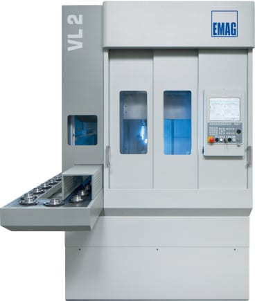 The VL 2 is a pick-up turning machine with which the EMAG engineers are fulfilling a combination of two extreme demands: highest possible output rates on the smallest possible footprint. “This is a truly all-important aspect,” confirms Dieter Kollmar. “Although the floor space requirement for this vertical turning machine is just about 5 square meters, it is a machine of substantial capability, including a fully comprehensive automation concept with conveyor belt, workpiece storage and pick-up spindle. In combination with vertical turning, this results in very fast machining processes. “In other words, short loading travel guarantees the lowest possible component cost. Compared to horizontal turning machines, productivity rates increase quite noticeably. And maintaining the VL 2 is simple. All service units are freely and quickly accessible. The user can set up the machine in one step. “That too is important, when productivity levels enter the equation. Operators without prior experience, working at a new and unfamiliar location, will be able to quickly familiarize themselves with the machine. All in all, this is an optimal solution for those who want to extend production with as little investment as possible,” notes Kollmar.
VT 2-4: For demanding shaft production
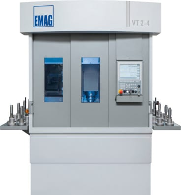 A similar approach is shown with the VT 2-4 Vertical Turning Machine, with which the EMAG specialists have created an equally fast manufacturing system for shaft production. Even demanding machining processes can be realized on it. When machining shafts up to 400 mm length and 63 mm diameter, component costs reduce considerably, with extremely short chip-to-chip times (as with the VL 2) being the reason. Workpiece grippers transport the workpieces into the machine and remove them again, once they have been machined. Depending on the workpiece, the changeover can be accomplished in just 6 seconds. And the actual turning process is fast, too. 4-axis machining allows the component to be machined from two sides simultaneously. Vertical alignment of the workpieces provides consistent process integrity, as the unrestricted chip flow prevents the formation of clusters in the machining area.
Central project management
 “We are convinced that these EMAG solutions are optimally designed to cover not only the specific requirements of an emerging market, but also those of Europe and the USA,” as Dieter Kollmar his company’s philosophy. Everything is greatly simplified, starting with production planning, as there is no need for separate workpiece and finished component storage, with the added advantage of a reduced floor space requirement. At the same time, the EMAG Group engineers act as central project developers, having access to machines with optimal interfaces. This guarantees a fast run-in and makes the machines maintenance-friendly. “When it is a question of arriving quickly at a wholly integrated, highly effective manufacturing solution, this approach must – from our point of view – be the first choice,“ Kollmar concludes.
For more information, please contact:
Kristal Kilgore
EMAG LLC
38800 Grand River Avenue
Farmington Hills, MI 48335
Tel: (248) 875-0313
Fax: (248) 477-7784
E-mail: kkilgore@emag.com
Web: www.emag.com
CAROL STREAM, ILLINOIS — Firth Rixson Metals, a global leader in specialty metals manufacturing and distribution based in the United Kingdom, and Banner Medical, a leading provider of supply chain solutions for medical-grade materials to the device, implant, and instrument industry, announce their exclusivity agreement for sales and marketing for Cobalt Chrome in the United States, effective January 1st, 2014.
“The medical-grade metal materials that Firth Rixson Metals produces are of the highest standards. By combining this offering with Banner Medical’s expertise in quality assurance, we will meet the stringent demands of the medical industry,” stated Elinor Oldroyd, GM of Firth Rixson Metals.
“Banner Medical specializes in medical-grade materials and offers deep expertise in the quality management that is necessary to fully comply with FDA 21 CFR 820. The depth, breadth and detail of Banner’s approach to quality management and supply chain management is unique and that distinction justifies the patent-pending status of Banner’s Essential Quality Systems,” says Banner Medical Executive Vice President / Chief Operating Officer Dan Stoettner. “Firth Rixson shares our commitment to vigilance and quality in both products and service.”
The Firth Rixson-Banner Medical agreement focuses on the Device industry’s need for precision-ground cobalt chrome materials. Stoettner went on to say, “Given the importance of cobalt chrome to today’s device, implant and instrument industry, we strongly believe that the Firth Rixson-Banner Medical alliance can help our customers realize true supply chain control on Cobalt Chrome materials, making them able to effectively address the unprecedented FDA scrutiny which exists today in the United States.”
—
![]() Firth Rixson’s technological and operational excellence, combined with the firm’s economies of scale, has made the company the metals provider of choice for demanding customers in diverse specialized industries in more than 40 countries.
Firth Rixson’s technological and operational excellence, combined with the firm’s economies of scale, has made the company the metals provider of choice for demanding customers in diverse specialized industries in more than 40 countries.
![]() Banner Medical serves the medical device, implant, and instrument industry with medical-grade metal materials; Banner Medical is ISO 13485 and ISO 9001 certified, and FDA CFR part 820 compliant.
Banner Medical serves the medical device, implant, and instrument industry with medical-grade metal materials; Banner Medical is ISO 13485 and ISO 9001 certified, and FDA CFR part 820 compliant.
For more information:
BILL NORLANDER
Medical Products Specialist
BANNER MEDICAL
494 East Lies Road
Carol Stream, IL 60188-9425
P: 630.868.1230
F: 630.653.7555
E: bnorlander@banner-medical.com
MIKE HADLEY
Supply Chain Manager
BANNER MEDICAL
494 East Lies Road
Carol Stream, IL 60188-9425
P: 630.868.1229
F: 630.653.7555
E: mhadley@banner-medical.com

VA 700 T – Joining machine for the manufacture of composite camshafts. While one cam is heat shrinking, the next one is preheated. Equipping the heat shrinking machine with a number of preheating units allows for the optimal application of this technology to suit the task at hand.
The composite camshaft is still gaining ground in the marketplace. The main reason for this is the considerable weight reduction it brings, compared to its one-piece rival. The composite version is by now also widely used in the HGV sector. However, the main disadvantage of many current assembly processes is the high joining force applied, which creates unacceptable tolerances in positioning and alignment of the cams. By contrast, the patented heat shrink assembly process from EMAG offers a decisive advantage, as it ensures that “ready-to-fit” camshafts, gear shafts and other precision composite units can be produced without problems.
The advantages of the composite camshaft are well known: less expense, less weight, the possibility to use different materials for the various constituent components, greater flexibility in production and the ability to implement new cam geometries, such as negative radii, with ease. The necessary reduction in fuel consumption – and with it those of CO2 emissions – are easier to achieve with an increasing use of composite camshafts.

Also used for gear shafts, heat shrinking of the constituent components ensures a compact design and high functional density, as the gears are in direct contact with the shoulders.
Alternative processes for the joining of cam and shaft have one serious disadvantage: the two components cannot be joined with the necessary accuracy to avoid a subsequent finish grinding process. In many cases, the joining of cam to tube is carried out using a form-fit process like press-fitting, knurling and/or spline/serrated gearing. The joining forces required for these processes can deform the components and result in unacceptable tolerances in cam position and orientation.
The heat shrink assembly process from EMAG means precision joining
Thermal joining, i.e. the heat shrinking of cam onto tube, ensures that the required tolerances are achieved with a reaction force-free process. The know-how to tightly control the process parameters of “temperature” and “time” – and the mechanical design of the joining equipment – are of the utmost importance in this process.
An optimal combination of robot and special-concept gripping technology allows for fusion gaps of < 15 µm to be achieved safely. The concept’s great flexibility allows camshaft designers more freedom in their designs and ensures that the process can also be used for medium batch sizes, where frequent component type changes are the order of the day. The high degree of precision of the composite camshaft drastically reduces the need to subsequently grind the cams or – where precision cams are used – does away with the requirement completely. A further advantage of this process lies in the possibility of using different materials for the composite shaft. This includes forged cams, for instance in 100Cr6, or finish-ground cams, even dimensionally accurate sintered cams that do not require a downstream finish-grinding operation. Secondary components, such as bungs and endpieces, can – just like the actual shaft itself – be made of more advantageous materials.
All this allows the camshaft to be made to suit the requirements of the engine and to optimize it in terms of load bearing capacity and manufacturing costs.
And now one step further:
Where the camshaft needs to be ground after heat shrink assembly, the joining machine can be linked up to a grinder. This is particularly easy when using an EMAG grinding center of the VTC DS Series. With this setup, the joining machine robot transfers the assembled camshaft directly to the loading position on the grinding center. The advantages of this process from EMAG also apply to the machining of other components. When machining gear shafts, ground gears can be joined tightly on the shaft, without needing to account for the grinding wheel overrun at the design stage. It also minimizes the length of the shaft and makes the whole unit more compact.

Ready-to-fit, complete, heat shrunk assembled camshaft. The high degree of precision of the composite camshaft drastically reduces the need to subsequently grind the cams or – where precision cams are used – does away with the requirement altogether.
Maximum flexibility
The EMAG process is characterized by only a very few machining components being in direct contact with the workpiece. It allows for the machines to be reset in the shortest possible time (typically less than 15 minutes).
Joining in seconds and achieving the highest possible quality
The heat shrink assembly process offered by EMAG combines flexibility with productivity, while freedom of design and choice of production technologies ensure a short cycle time. While one cam is heat shrinking, the next one is already being preheated. Equipping the heat shrinking machine with a number of preheating units allows for the optimal application of this technology to the task at hand. It is these advantages that may well be the reason why so many firmly established manufacturers of camshafts and other precision assemblies are showing such a great interest in the new process, are asking for machining tests, or are already applying the process under actual production conditions. In the ideal case, the customer will take advantage of the synergy provided by the EMAG Group and ask for a complete concept to be prepared that covers everything from pre-machining to heat shrinking and end machining.

Finished assembly of a motorcycle camshaft. An optimal combination of robot and special-concept gripping technology allows the pieces to join with a fusion gap of
The advantages of the heat shrink process:
The advantages of the composite camshaft:
For more information, please contact:
Kristal Kilgore
EMAG LLC
38800 Grand River Avenue
Farmington Hills, MI 48335
Tel: (248) 875-0313
Fax: (248) 477-7784
E-mail: kkilgore@emag.com
Web: www.emag.comEMAG LLC
38800 Grand River Avenue
Farmington Hills, MI 48335
Tel: (248) 875-0313
Fax: (248) 477-7784
E-mail: info@usa.emag.com
Web: www.emag.com
Attention: Peter Loetzner
Continue reading No. 1027 is a 550ºF electric cabinet oven from Grieve, currently used for drying pellets in pans at the customer’s facility. Workspace dimensions on this oven measure 47” W x 30” D x 63” H. 30 KW are installed in Incoloy-sheathed tubular elements to heat the oven chamber, while a 2000 CFM, 2-HP recirculating blower provides horizontal airflow across the workload.
This Grieve cabinet oven features 6” insulated walls, aluminized steel exterior, Type 304, 2B finish stainless steel interior, four independent doors for access to the workspace and eight 20” wide x 30” long x 1” high loading pans on channel supports in each oven opening.
Controls onboard No. 1027 include a digital indicating temperature controller, manual reset excess temperature controller with separate contactors and recirculating blower airflow safety switch.
For more information, please contact:
THE GRIEVE CORPORATION
500 Hart Road
Round Lake, IL 60073-2898
Phone: (847) 546-8225
Fax: (847) 546-9210
Web: www.grievecorp.com
Email: sales@grievecorp.com
Attention: Frank Calabrese, VP
Gümmilast material from Kastalon offers metalformers greater levels of performance and wear characteristics, compared to conventional polyurethane or Neoprene forming pads and fluid cells.
Short run forming of complex sheet metal shapes using rubber dies and pads is quick and highly effective. This technique was first accomplished using the Guerin Process. After the Second World War, the Wheelon process was developed as an improvement over the Guerin Process. A Wheelon press is capable of manufacturing large, complex, short run parts with economic tooling. This type of hydraulically actuated bladder forming is widely used in the aerospace industry today.
When the Wheelon process was first employed, the forming press fluid cells and forming pads were made of Neoprene rubber. The Neoprene formulations of the day were developed by rubber molders’ chemists. Their formulas were proprietary and highly secretive.
The high grade formulation of Neoprene used was an excellent material for the function of forming pads and fluid cells. It was tough, had very high extensibility, good cut resistance, excellent oil resistance and produced good detail with moderate pressures.
This was the standard material for Wheelon forming pads and fluid cells for many years. However, as the U.S. industrial rubber goods industry matured, its productive capacity diminished. The industry lost the capacity and knowledge required to make Neoprene pads and cells. There are presently no suppliers of rubber Wheelon or Guerin cells or pads in North America.
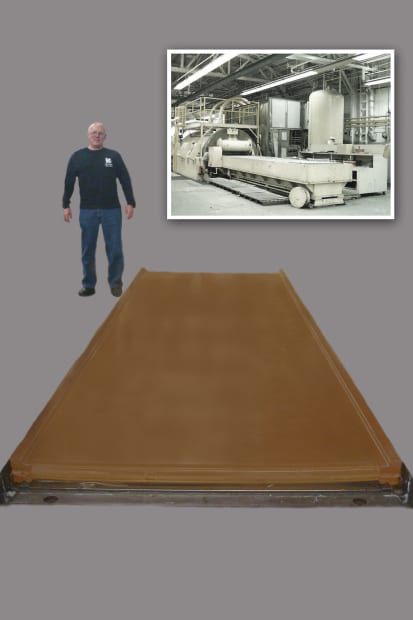
Product shown in use in the Wheelon process, one used extensively in the aerospace and other industries.
Fortunately, there was capacity to produce these parts from polyurethane. Polyurethane is a synthetic elastomer that is far stronger than Neoprene. Polyurethane has greater cut resistance, more abrasion resistance, greater tensile strength and has suitably high elongation for effective use in the Wheelon process.
Polyurethane is also a more environmentally stable material than the original Neoprene. Most often, when installing forming pads and upon starting forming operations, the Neoprene would be “dried out”. This would lead to shrinkage of the pad and increased stiffness. In order to install the pad and/or start the operation, it would be necessary to heat the Neoprene to restore it to its original softness and resilience. Polyurethane is far more consistent, retaining its size, shape and maintaining its softness and resilience. This eliminates the need for heat “rejuvenation”.
However, in spite of the superiority of the physical properties of polyurethane over the previously used Neoprene, there is a drawback to polyurethane. Due to its increased strength and toughness, far greater pressures must be employed to achieve acceptable part definition and this results in greater strain on the press, its components and some reduction in forming definition.
Some of the difficulties encountered with the use of commercial and even Kastalon KAS43210AE forming pads and cells are:
The challenge to industry has been to create a material that has polyurethane’s toughness and the extensibility of the lost Neoprene material.
Our initial discoveries led us to improve the traditional polyurethane formulations to increase extensibility, reduce working pressure and improve cut and tear strength in the “mid extension” ranges where these pads operate. However, this was only a compromise and a temporary solution to producing a forming pad with superior performance.
After years of continuing research, a hybrid polyurethane compound, trademarked Gümmilast by Kastalon, has been developed. The properties of Gümmilast are very similar to the original Neoprene in performance and exceed the toughness of traditional polyurethane. A comparison of the original Neoprene, Gümmilast, Kastalon KAS43210AE and commercial polyurethane is presented in the following table.
Physical Properties: Traditional Neoprene vs. Polyurethane
| Neoprene | Gümmilast KAS021909A | Kastalon KAS43210AE | Commercial PUR | |
| Hardness,Shore ATensile, psi | 55-602,002 psi | 602850 | 704153 | 704660 |
| Elongation | 773 % | 774 | 694 | 630 |
| 25% modulus | 92 psi | 133 | 201 | 221 |
| 50% | 119 psi | 184 | 260 | 282 |
| 100% | 157 psi | 229 | 340 | 360 |
| 200% | 277 psi | 262 | 434 | 475 |
| 300% | 472 psi | 337 | 522 | 670 |
| 400% | 741 psi | 471 | 738 | 985 |
| Split tear | 228 psi | 191 | 181 | 185 |
| Dynamic modulus | 289 | 372 | 733 | 836 |
The similarity between Gümmilast and the original Neoprene is apparent. In the operating range extension (250-400%), previously available polyurethanes create far higher internal stresses. The rapid increase of these stresses in this operational strain range leads to need for higher pressure and less definition. This makes tool design and the use of intensifier pads highly critical.
When using Gümmilast, the reduction in operating pressure will yield greater press life, while offering greater part definition.
Life testing of Gümmilast pads and cells is ongoing. To date, Kastalon anticipates 3-6 times the life of Improved Kastalon Polyurethane and an even greater life over commercial polyurethane.
In conclusion, Kastalon Gümmilast will provide the Wheelon Process user with a material that offers similar process ease, forming definition and reparability as experienced with the original rubber and providing significantly improved life over commercial polyurethane. Gümmilast is also available for hydroforming bladders, throw pads and Guerin Process pads.
Kastalon Gümmilast products are available from your press parts provider or from Kastalon, Inc.
For more information on this product, please contact:
KASTALON, INC.
4100 W. 124th Place
Alsip, IL 60803
Phone: 708-389-2210
Fax: 708-389-0432
Web: www.kastalon.com/engineering-guide.php
Email: sales@kastalon.com
Attention: Marty Pokorney
EMAG has a long history, starting back in 1867 in Bautzen, Germany, as an iron foundry and engineering works. Re-established 60 years ago in Eislingen, Germany, in 1952 to make lathes and special-purpose machines, today it makes manufacturing systems for precision metal components from its headquarters in Salach, Germany. Its machines range from basic round-part vertical turning centers to machining centers with as many as six axes handling large workpieces. They perform turning, milling, grinding, hobbing, drilling and more as singular purpose setup or combination machines.
 The tools manufacture primarily automotive, off-highway, agricultural and oil field components. For example, EMAG tools are involved in transmission components for agricultural vehicles, such as gears, ouput shafts and idlers. “If you look at a dozer from the outside, you have a chain,” notes Peter Loetzner, CEO of EMAG’s U.S. subsidiary in Farmington Hills, Mich. “There are two large precision wheels that drive that chain. There are idlers on the bottom. Our machine can make all these round components.”
EMAG’s equipment differs from typical vertical lathe machining centers, whose head stock is mounted, typically horizontally, and a turret turns to do the machining. “Our turret is mounted in a concrete base, so it’s not moving,” Loetzner explains. “We have a head stock that moves outside of that design. That gives us better precision and better tool life.”
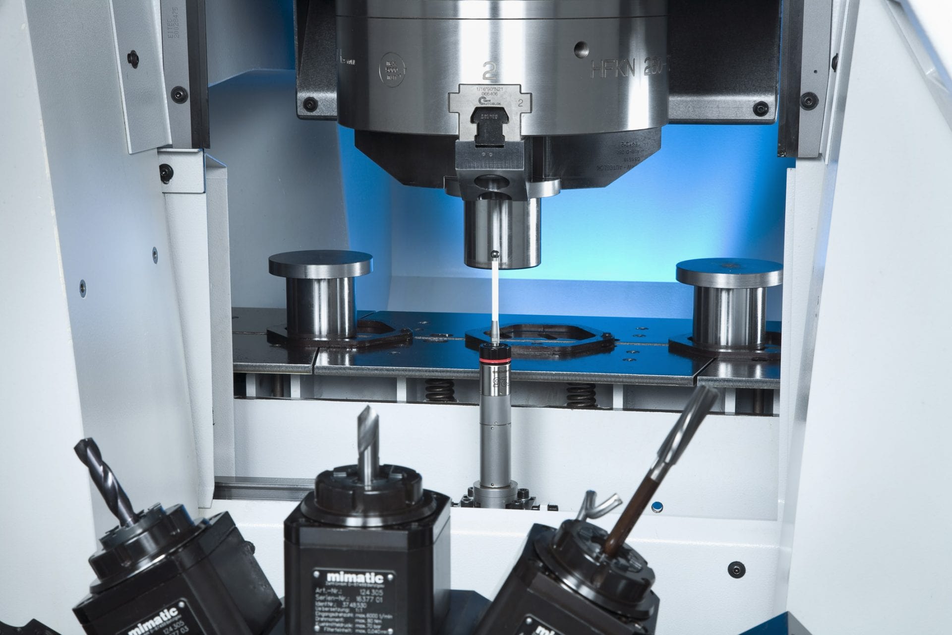
 The machine builder takes pride in its ability to produce high-precision parts. In one example, Axle Alliance in Redford, Mich., needed to hold to a 25 µm tolerance for 390 mm diameter steel ring gears during hard turning, which is done prior to grinding the gear teeth. EMAG worked with Axle Alliance to develop a probing process that ultimately delivered a variation of less than 15 µm. Axle Alliance now uses six machines built at EMAG’s headquarters in Germany, each dedicated to a part line.
Another example comes from Precima Magnettechnik in Brückeburg, Germany, whose customers expect absolute perfection from, in this case, housings for brakes used mainly for wind turbines. Precima had had issues with machine vibration causing negative effects on tool life and surface finish. However, the rigidity of EMAG’s turning machines and the vibration damping quality of the base allows for the very high feed rates and cutting speeds required in precision hard-machining. Precima now runs four vertical pick-up turning machines from EMAG.
 Loetzner gives much of the credit for the machines’ capabilities to long-time partner Siemens. EMAG has standardized on the Siemens Sinumerik 840D CNC platform, specifically the solution line and power line. Loetzner likes, in particular, that the CNC controller is an integral part of the PLC, and they are able to do almost everything through the CNC, including making it look like a PC for the operator. The common look and feel for the operators makes for easier onsite commissioning and cross-training, Loetzner adds.
In one recent case study, EMAG needed to provide grinding, turning and turn-grind machines to a major agricultural equipment builder, and the machine builder relied on the 840D CNC. “We needed to devise a control solution that would satisfy all the needs of the various machines we were supplying to this demanding customer, based on a common platform, to enable easier design, integration, startup, commissioning on-site and training for our customer’s operations and maintenance personnel,” Loetzner said at the time.
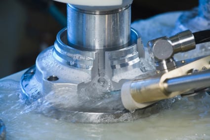
 Similar control technologies are used on EMAG’s newer-technology machines, including laser welding and electrochemical machining centers. These technologies have little impact on the control or automation schemes, Loetzner notes, because they still are essentially performing the same task, whether in a dry, lubed, gas-cooled or underwater environment. Only the sensors and encoders need to change to accurately feed the relevant data to the control. In fact, the controls are often much simpler because the axes of motion are fewer, though more multi-axis and workpiece manipulating machines are being developed.
The CNC also enables remote monitoring over a wireless network so that process engineers can see what the operator sees on each machine. The agricultural equipment customer mentioned has used the remote monitoring capability on a wide variety of EMAG machines for several years, with all data communicated through a single information network that’s accessible by both EMAG and Siemens. Through this arrangement, they have been able to significantly reduce downtime, service calls and troubleshooting identification time.
 More than 75% of the EMAG machines at this customer site are equipped with robotic devices. The lights-out capabilities this provide make remote monitoring that much more important. Remote monitoring can be done directly through the Sinumerik CNC in a one-on-one exchange with the customer, Loetzner notes, or even a three-way exchange involving Siemens as well.
While happy with the precision capabilities, EMAG’s focus on future development is trying to decrease the downtime between producing components. “On the automation and the part handling, the challenge is you want the machine to run and make parts all the time, right? But once a part is done, you have to take it out and put the other in,” Loetzner says. “Those non-productive times are the biggest enemies.”
 EMAG reduces those times partly by use of the Japanese chaku chaku principle. Meaning “loading loading,” the idea is to bring various process steps as close together as possible to improve the speed between the processes. EMAG’s vertical machining centers not only fill a much smaller footprint on the plant floor, they also improve chip flow. Also, all of EMAG’s machines are self-loading, with a servo-controlled shuttle traveling through the machine, but not through the work envelope, Loetzner notes.
“While we have shown the industry we can master any part to highest precision, over the last five years we’ve been more and more focused on tightening non-productive time,” Loetzner says. At IMTS in Chicago in September, 2012, EMAG showed a new machine generation that significantly reduces the non-value add times. “Our chip-to-chip time was between 6 and 7 seconds for typical automotive gear,” Loetzner says. “Now it would be a second or less.”
For more information:
Kristal Kilgore
EMAG LLC
38800 Grand River Avenue
Farmington Hills, MI 48335
Tel: (248) 875-0313
Fax: (248) 477-7784
E-mail: kkilgore@emag.com
Web: www.emag.com
Check out Cutting Tool Engineering’s coverage of EMAG’s VL 2 P at IMTS 2012 HERE.
Contact for press and publishers:
EMAG LLC
38800 Grand River Avenue
Farmington Hills, MI 48335
Tel: (248) 875-0313
Fax: (248) 477-7784
E-mail: info@usa.emag.com
Web: www.emag.com
Attention: Peter Loetzner
Continue reading