Contact us today:
(847) 934-4500
tdaro@bernardandcompany.com

Contact us today:
(847) 934-4500
tdaro@bernardandcompany.com
No. 863 is an electrically-heated 1400°F(~760°C) box furnace from Grieve, currently used for preheating molds. 52 KW are installed in nickel chrome wire coils supported by a stainless steel frame. A
The unit has 7” thick insulated walls with stainless steel covers. The oven was specially built with inert atmosphere construction. This consists of a continuously welded outer shell, high temperature door gasket, sealed heater terminal boxes, inert atmosphere inlet and inert atmosphere outlet.
Controls onboard No. 863 include a motor-operated vertical lift door and a 4-point strip chart recorder.
For more information, please contact: THE GRIEVE CORPORATION, 500 Hart Road, Round Lake, Illinois 60073-2835 USA. Phone: (847) 546-8225. Fax: (847) 546-9210. Web:www.grievecorp.com. Email: sales@grievecorp.com. Attention: Frank Calabrese.
Continue readingNo. 983 is an electrically-heated 550°F(~287.78°C) bench oven from Grieve, currently used for curing medical instruments. 3KW are installed in Incoloy sheathed tubular heating elements. 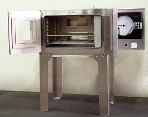
The oven has 3” insulated walls, a Type 304, 2B finish stainless steel interior and a #4 brushed finish stainless steel exterior. Two 13” x 4” access slots are equipped with insulated covers on the rear wall of the oven. An 8” x 10” double-pane Pyrex window is used for viewing the oven chamber. An interior oven light is also provided.
Controls onboard No. 983 include recording and programming temperature controllers and a recirculating blower for this oven.
For more information, please contact: THE GRIEVE CORPORATION, 500 Hart
Road, Round Lake, Illinois 60073-2835 USA. Phone: (847) 546-8225. Fax: (847) 546-
9210. Web: www.grievecorp.com. Email: sales@grievecorp.com. Attention: Frank
Calabrese.
-0-
Photo enclosed
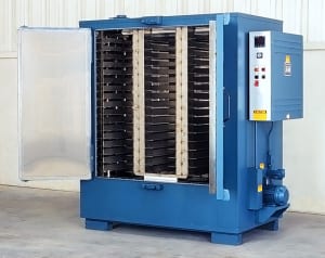
The unit has 4” insulated walls and a Type 430 stainless steel interior. A 1000 CFM, 1-HP recirculating blower provides horizontal airflow to the workload. Stainless steel pans are held by three tiers of seventeen shelf supports on a 3” vertical center.
Controls onboard No. 834 include a digital indicating temperature controller, recirculating blower airflow safety switch and a manual reset excess temperature controller with separate contactors.
For more information, please contact: THE GRIEVE CORPORATION, 500 Hart Road, Round Lake, Illinois 60073-2835 USA. Phone: (847) 546-8225. Fax: (847) 546-9210. Web: www.grievecorp.com. Email: sales@grievecorp.com. Attention: Frank Calabrese.
NEWS RELEASE: THE GRIEVE CORPORATION
Agency contact: Tim Daro 847-934-4500
Continue reading
In response to the gear market’s need for optimization software, which has been lacking for many years, Excel-LentTM gear/gearbox design and analysis software has been developed by Excel Gear, Inc. (Roscoe, IL) and written in Visual Basics.Net. This software has been written by engineers who also design and manufacture gears for their own use, according to company president N.K. “Chinn” Chinnusamy.
Mr. Chinnusamy further comments, “Although commercial software has long been available in the gear industry, it has been too expensive or too complicated to be used by engineers without specialized gear design knowledge. Our software is specifically designed with a user-friendly interactive input screen providing defaults and options in accordance with the AGMA 2001 standard (American Gear Manufacturers Association).” The users of Excel-Lent software can easily navigate through the input screens to edit, analyze and produce reports on the optimum gear and gearbox design for various industrial and other applications.
“This software is not designed for any specific industry,” continues Chinnusamy. It can be used for machine tools, heavy materials handling equipment or even the wind turbine industry. For the wind turbine industry, for example, the designer needs a full understanding of all the operating loads on the gear members to arrive at the required power rating.
The key calculations performed are the AGMA power rating and load calculations, including bending strength geometry factor (J) and pitting resistance geometry factors (I). Output from the software is a single page of data printed in a format that is easy to read and interpret. Other commercial software typically prints five or six pages of information, which may be confusing to most design engineers unless they are gear experts, Chinnusamy further observed.
The users of Excel-Lent need not be familiar with AGMA standards to use this software. Those who are not gear engineers can also benefit from the gear engineering knowledge embedded in the software package.
Excel-Lent contains three sections – design, analysis and gear dimensions. Any of the sections can be used individually to run calculations. On a typical job, according to Excel Gear, hundreds of hours typically spent doing the calculations can be saved.
The three sections are detailed below:
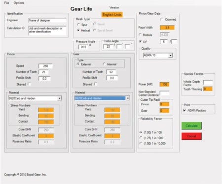
Key values calculated are the diameter and face width of the pinion required to achieve the surface fatigue power rating and optimized DP or module (based on the calculated diameter) required for the bending fatigue power rating. The data are automatically exported to the analysis program for detailed analysis. The results are the power ratings for 5,000 -100,000 hours of B1 life (reliability factor of 1).
If required, other values such as face width or center distance may be entered but Excel Gear recommends leaving the face width and center distance values blank for optimized gear design. Design and analysis programs are used to design one gear stage in sequence on an external or internal spur and helical gear mesh.
ANALYSIS: This program calculates the power rating of a gear set for 5,000, 10,000, 25,000, 50,000 and 100,000 hours of B1 life (reliability factor of 1). Reliability factor of 1, 1.25, or 1.5 can be selected, as required. The user needs to input mesh type (spur, helical, internal and external), pressure angle, helix angle (if applicable), pinion speed, number of teeth in pinion and gear, material (from the list provided in the software), face width, DP or module and quality required. Crown and/or profile shift, if used, can also be entered. The program will calculate the power rating of the gear set and show HP or KW capability along with torque, tangential force and static capacity. Static capacity is based on yield strength and, if bending stress exceeds yield strength at any time, permanent deformation or even tooth breakage may occur. If the results are satisfactory, the user can print the single page results only or, optionally, also print all the AGMA factors used in making the calculations.
Most commercially available gear software will generate five or six pages of output along with required bending and surface fatigue strength of the gear set. The user therefore needs knowledge of metallurgy to select proper material and heat treatment or must consult a metallurgist. By contrast, the Excel-Lent software program lists commonly used gear material for the user to select. If the results are not as required, the user can select another material or change other design criteri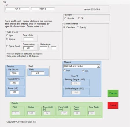
DIMENSIONS: In the opinion of the manufacturer, this Excel-Lent gear dimension software is the most versatile program available in the market. The program will calculate the manufacturing dimensions for a new pinion and gear or calculate the dimension of a pinion or gear to mate an existing pinion or gear. This can be done for external gears, internal gears or a gear rack. Users need only to enter the type of mesh (spur or helical, internal of external), pressure angle, helix angle(if helical gears), number of teeth in pinion and mating gear, DP or module and the quality of the gears.
The program will then calculate the center distance, dimension over pins, span measurement, form diameter, roll angles and all gear tolerances to match the quality required (AGMA, DIN, or ISO). The program will calculate the helix angle required to match a specified center distance if the user chooses that option.
The program displays plain English error messages when input is questionable or in error. For example, if the center distance is incorrect, the program will flash error messages such as, “Center distance specified is too large/small.”
The program calculates optimized profile shifts for pinion and gear operating at a non-standard center distance, if the operating center distance is specified. If the profile shift required to operate is large and makes the top land narrow, the program will flash warning messages and display the proper profile shift amount to avoid narrow top land.
Excel-Lent software further provides users the option to balance beam strength or specific sliding of gear and pinion, if desired. This is a key requirement for wind turbine gears. The program will also calculate gear blank tolerances to achieve the desired quality level, if shaft and bore diameters are entered. Users can switch between inch and metric dimensions with one click.
For further information or a test demo, available on CD or onsite, please contact:
EXCEL GEAR, INC.
11865 Main Street
Roscoe, IL 61073
Phone: 815-623-3414
Fax: 815-623-3314
Web: www.excelgear.com
Email: sales@excelgear.com
Attention: N.K. Chinnusamy or Bill Powers
ABOUT EXCEL GEAR
Excel Gear brings over 50 years of machine tool experience to the design, manufacturing and quality analysis of its various gear, gearbox, fluid bearing, spindle, CNC gimbal head, nutator and special equipment production. ANSYS software for FEA on stress, strain, deflection, as well as modal analysis, time and frequency domain, our Spindle Analysis Program, MATLAB/Simulink, AutoCAD/SolidWorks/CADAM and other programs are all utilized to affect the best solutions to customer requirements. Excel also builds two-axis CNC gimbal heads with 20,000 RPM motorized spindle, 15,000 RPM cartridge type spindle assemblies and CNC rotary tables for major machine tool companies. Our high-accuracy gear grinding equipment produces to AGMA 15 (DIN 2) tolerances for quality that meets or exceeds the increasing customer demands for high-speed and high power transmission with smooth, quiet operation. Recently, the company has entered the emerging wind turbine market to provide various gears and gearbox components, as well as extensive maintenance and system performance engineering assistance.
PR agency:
Tim Daro
Bernard & Company
tdaro@bernardandcompany.com
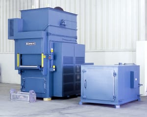
The unit has 4” insulated walls and an aluminized steel interior and exterior. It is also equipped with a removable top-mounted heat chamber (shown on floor in photo) and a motor-operated vertical lift door.
A 4200 CFM, 3-HP recirculating blower provides vertical upward airflow to the workload. Ten 200 lb. capacity carriers with roller surfaces, 31” wide x 14” long, are supported on each side by a heavy-duty roller chain. The carriers are driven through the conveyor by a 3/4-HP drive motor controlled by a variable frequency drive. Fifteen loading baskets are included with the oven. A loading table with rollers lines up with the rollers on the carriers and a latch holds the baskets in place on the carrier.
Controls onboard No. 961 include a digital temperature controller, recirculating blower airflow safety switch, 10” diameter circular chart recorder and a manual reset excess temperature controller with separate contactors.
For more information, please contact: THE GRIEVE CORPORATION, 500 Hart
Road, Round Lake, Illinois 60073-2835 USA. Phone: (847) 546-8225. Fax: (847) 546-
9210. Web: www.grievecorp.com. Email: sales@grievecorp.com. Attention: Frank
Calabrese.
Argus Subsea uses hydraulic rod locks from AME to secure underwater oilfield trees at 5000-6000’ depths to 3000 psi and 50,000 pounds of axial holding
Argus Subsea produces its AZ-10 fully concentric, vertical mono-bore subsea tree design for rapid field development. Originally designed for low net present value (NPV), marginal and smaller fields, where the capital investment containment is critical and the need exists for off-the-shelf hardware, the AZ-10 can be run on any rig, regardless of moonpool size or accessibility through a V-door or port side. Essentially, according to Earl Broussard, the company’s director of sales & marketing, “Anywhere a rig can power a BOP, the AZ-10 can operate effectively. And, being a standard horizontal tree design with a universal tubing hanger system that runs in any 18-3/4”, 10,000 or 15,000 psi wellhead, with a concentric design for all downhole and tubing hanger-to-tree interface, it can be quickly put into service.” In fact, the company’s literature boasts a typical reduction in time to first oil of fifteen months, with lower CAPEX and OPEX costs, less drilling and wellhead completion cost, plus reduced third-party cost.
The AZ-10 is currently rated at 10,000 psi working pressure and 6000’ water depth and is designed to the standards of API 17D, API 6A, PR2, NACE MR0175 and AV1 PR-2 USV. The unit weighs approximately 50,000 pounds and is light enough to be handled safely with rig cranes and easily transported to the moonpool. The AZ-10 can be deployed through any Generation-2 semi-submersible or newer generation rig’s moon pool. A much simpler design than most horizontal or vertical trees, the AZ-10 requires only five running tools versus 20-30 typically found on comparable subsea tree systems. The units are designed for 20 years of service life in production, injection or well test operations.
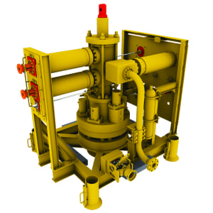
AMLOK rod lock highlighted on tree. Each rod lock operates to 3000 psi and provides 50,000 pounds of axial holding force at depths of 5000-6000’. Special construction, porting and heat treatment were utilized in the manufacture of these devices.
The hanger system operates on a lock and seal system that uses mechanical and hydraulic sealing within the tubing hanger. A key component designed into the AZ-10 is the AMLOK® hydraulic rod lock, provided by Advanced Machine & Engineering (AME) of Rockford, Illinois, a designer and builder of various rod locks for both hydraulic and pneumatic holding, in the event of a power loss. AME rod locks are typically found on all types of off-highway and construction equipment, as well as materials handling devices, machine tools and elsewhere, used to secure a cylinder rod in place to prevent further motion.
For the application on the Argus Subsea trees, according to Shane Hatfield, AME sales manager, several challenges were apparent and a few were not. The obvious obstacles were the depth and the pressures involved. The maximum load was to be 3000 psi and the axial holding force approximately 50,000 pounds at typical depths in the 5000-6000’ range. To address these issues, AME engineered the rod locks from 4140 steel with electroless nickel plating and a specially formulated two-part epoxy to create a completely sealed unit. Marine grade lubricant was used. “Those were the easy parts,” muses Hatfield.
With the external sealing system of the AZ-10 and the wide variety of connections involved, the construction of the rod lock also needed to accommodate the unique challenges of force over distance in a wide window of installation conditions. Since the customer was very cost-sensitive, it was necessary for AME engineers to create a one-size-works-for-all unit and this presented considerable application engineering challenges. “This was the hard part,” recalls Hatfield.
Working with Chance Burton, the driving force behind the original engineering effort at Azura, the predecessor company to Argus, Hatfield and his team demonstrated AMLOK rod locks as the only design that worked immediately over the entire range of performance scenarios. 1500 psi release and 3000 psi compressive were needed to satisfy all conditions and the AME engineers successfully satisfied these criteria. Key factors in the success of the AMLOK design here are the special porting and autoclave treatment used.
After an initial order of 10 units (2-4 used per tree), the business has remained steady, according to Hatfield. These rod locks have been used successfully on numerous installations of the AZ-10, where the connections to numerous wellhead equipment brands have varied considerably.
As the attached diagrams demonstrate, AME rod locks are actuated by a spring/collet mechanism upon loss of hydraulic power and unclamped by the restored pressure. They are built to accomplish a mechanical locking, holding a cylinder rod or machine shaft in position, up to the rated load, until power is restored and the locking mechanism released.
For more information on the subsea trees referenced in this story, please contact:
ARGUS SUBSEA 5510 Clara Road Houston, TX 77041 Phone: 713-983-7222 Fax: 713-983-7007 Email: info@argussubsea.com Web: www.argussubsea.com Attention: Earl Broussard, Director of Sales & Marketing
For more information on the rod locks referenced in this story, please contact:
Shane Hatfield, Sales Manager
ADVANCED MACHINE & ENGINEERING CO.
2500 Latham Street Rockford, IL 61103
Toll-Free: 800-225-4263
Phone: 815-962-6076
Fax: 815-962-6483
Email: shane@ame.com
Web: www.ame.com
AME-Advanced Machine & Engineering Co., is a manufacturer located in Rockford, Ill., serving the Machine Tool Industry with precision components and accessories, including spindle interface components, workholding devices and, through our sister company, Hennig, machine enclosures, chip removal and filtration systems. The Fluid Power – Safety markets are served with cylinder rod locks and Safety Catcher devices; and the Production Saw market with our AmSaw carbide saw machines and Speedcut blade products. AME has manufacturing partners and service centers around the world and across the U.S. To learn more, visit www.ame.com.
Hennig, Inc. designs and produces custom machine protection and chip/coolant management products for state-of-the-art machine tools. Hennig products are designed to protect against corrosion, debris and common workplace contaminants. Manufacturing facilities are located in the U.S., Germany, France, Czech Republic, Brazil, India, Japan, China and South Korea. Repair centers are located in Machesney Park, IL; Chandler, OK; Livonia, MI; Blue Ash, OH; Mexico City, Mexico; and Saltillo, Mexico. To learn more, visit www.hennigworldwide.com.
Please direct all inquiries from this article to:
Tim Waterman
ADVANCED MACHINE & ENGINEERING CO.
2500 Latham St.
Rockford, IL 61103
Phone: 815-316-5277
Fax: 815-962-6483
E-mail: info@ame.com
Connect with AME online:
Global leader in carbide sawing systems acquired by leading machine tool component and carbide saw machine manufacturer
Advanced Machine & Engineering (AME), the Rockford, Illinois-based manufacturer of various machine tool components and auxiliary equipment, today announced the asset purchase of the Metalcut Carbide Saw Division of Centro-Metalcut, also of Rockford and a longtime global industry leader in the design and manufacture of heavy-duty carbide sawing systems for the metalcutting industries.
AME is also a leading global manufacturer of carbide sawing systems, under its popular AMSAW® brand name. AMSAW systems are found in forge, metalcasting, service center and primary producer operations, anywhere large or continuous sawing is performed. The acquisition of the Metalcut carbide saw line represents a substantial expansion of the company’s capabilities in the world market.
This purchase will transfer the complete sawing machine technologies, engineering data, inventory, spare parts and service operations for all Metalcut carbide saws to AME. Steve Swanson, the business unit manager for the carbide saw machine division of AME, will assume oversight responsibility for the Metalcut product line, allowing a seamless transition for all existing customers and immediate access to the Metalcut carbide saw line for all new AME accounts. AME has worldwide sales and service locations already in place to accommodate all customer requirements, according to Greg Champion, vice president of sales & marketing for the company.
Centro-Metalcut will continue to manufacture and market all other product lines in its offering, including hot and cold abrasive saws, conditioning grinders and materials handling equipment.
Dietmar Goellner, AME president and CEO, and Danny Pearse, CEO of Centro-Metalcut, agreed to the purchase terms on September 24, 2010.
For more information, please contact:
Tim Waterman
ADVANCED MACHINE & ENGINEERING CO.
2500 Latham St.
Rockford, IL 61103
Phone: 815-316-5277
Fax: 815-962-6483
E-mail: info@ame.com
Connect with AME online:
Advanced Machine & Engineering Co., is a manufacturer located in Rockford, Ill., serving the Machine Tool Industry with precision components and accessories, including spindle interface components, workholding devices, and, through our sister company, Hennig, machine enclosures, chip removal and filtration systems. The Fluid Power – Safety markets are served with cylinder rod locks and safety catcher devices; and the Production Saw market with our AmSaw carbide saw machines and Speedcut blade products. AME has manufacturing partners and customers around the world and across the U.S. To learn more, visit www.ame.com.
Hennig, Inc. designs and produces custom machine protection and chip/coolant management products for state-of-the-art machine tools. Hennig products are designed to protect against corrosion, debris and common workplace contaminants. Manufacturing facilities are located in the U.S., Germany, France, Czech Republic, Brazil, India, Japan, China and South Korea. Repair centers are located in Machesney Park, IL; Chandler, OK; Livonia, MI; Blue Ash, OH; Mexico City, Mexico; and Saltillo, Mexico. To learn more, visit www.hennigworldwide.com.
Continue reading
At a time when the media are constantly touting the imminent demise of American manufacturing, there are numerous suppliers to one of this country’s greatest and most universally sought after technological achievements who might challenge that notion. In fact, they just might debunk it with extreme prejudice. These are the suppliers to the Undulator System on the Linac Coherent Light Source (LCLS) project, recently completed at Argonne National Laboratory (ANL) and supplied as an extension of the SLAC National Accelerator Laboratory in California.
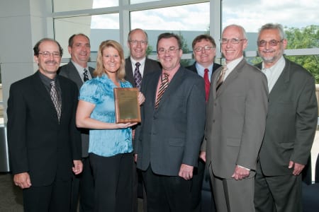
On Friday, September 3, at ANL in Lemont, Illinois, several vendors to this project were acknowledged for their roles, during a presentation made by various key individuals in the project’s start-up and ongoing development. One of these vendors is M-1 Tool Works of McHenry, Illinois, who supplied a variety of machined metal components and assemblies used in the focusing operation on the light beams that create ultra-bright, ultra-short x-ray pulses from a high-energy electron beam. These x-ray pulses are a billion times brighter than the most powerful light source known and are used to capture images of molecules and detail their actions within an atomic structure. The first beam was generated in April, 2009 and the undulator was installed and fully functioning in the Spring of 2010.
Users of this new American technology from every continent are already lining up at SLAC to apply it for the investigation of atoms on various mechanical structures, raw materials, pharmaceuticals, industrial chemicals, military ordnance, space exploration hardware and hundreds of other products. Commercial, institutional, educational, governmental and advanced research concerns are all requesting use of this technology, according to the directors of the project.
M-1 Tool Works, a longtime supplier of precision components to such diverse fields as the aerospace industry, defense, medical, high tech, close tolerance and high reliability commercial industries, had previously done work for Fermilab and Lawrence Livermore National Laboratory. They were called upon by ANL to produce 36 assemblies, each comprising a central assembly and various close tolerance components. The materials used included tool steel, stainless steel, aluminum and specially annealed oxygen-free copper for the particular densities and electrical properties required on this application.
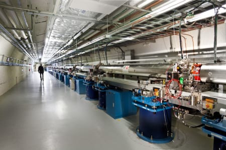
Functionally, the highly collimated electron beam travels through the undulator, where its motion is modified by a series of alternating magnets to create radiation saturation and the coherent alignment structure of the beam. This occurs in a two-mile section of the linear accelerator. First light was generated in April, 2009, light to the instrument was achieved in August of that year and the project was completed for commercial utilization in the summer of 2010. This $415 million project was completed by ANL on time and under budget.
Overall, the undulator section measures 433’ and runs in a 600’ section of the tunnel at SLAC. All the assemblies were built and tested at ANL in Illinois, then transported for assembly and final commissioning at Stanford. A Beam Position Monitor checks the dimension and orientation of the beam to sub-micron levels of accuracy.
For further information on this story, please contact:
M-1 TOOL WORKS INC.
1419 S. Belden Ave.
McHenry, IL 60050-8399
Phone: 815-344-1275
Fax: 815-344-1950
Web: www.m1toolworks.com
Email: ray.lindberg@m1toolworks.com
Attention: Ray Lindberg, Sales Manager
Agency contact:
Tim Daro
Bernard & Company
847-934-4500
tdaro@bernardandcompany.com

The unit has 7” insulated walls comprised of 5” of 2300°F ceramic fiber and 2” of 1700°F block insulation. The 6½” floor insulation is made of 4½” of 2300°F firebrick and 2” of 1900°F block insulation. The plate hearth is made of firebrick and is supported by firebrick piers.
Controls onboard No. 871 include a Partlow MRC 7000 recording and programming temperature controller and an electrically-operated vertical lift door.
For more information, please contact: THE GRIEVE CORPORATION, 500 Hart Road, Round Lake, Illinois 60073-2835 USA. Phone: (847) 546-8225. Fax: (847) 546-9210.
Web: www.grievecorp.com. Email: sales@grievecorp.com. Attention: Frank Calabrese.
Continue readingSinumerik MDynamics Milling Roadshow is coming to IMTS 2010.
If your company is looking for the way to more efficiently cut parts for aerospace, automotive or medical, one thing is certain — the demand for five-axis CNC machining has risen dramatically. And now there’s MDynamics: using one solid CAD/CAM/CNC process chain will get you to market faster than your five-axis competitors who will be lagging under a less integrated approach.
What is Sinumerik MDynamics?
“For users, it is extremely important to get from the blueprint to the finished part quickly, precisely and cost-effectively,” says John Meyer, marketing communications manager, Siemens Industry, Inc. “Sinumerik MDynamics combines our milling expertise together with our powerful Sinumerik CNC hardware platform, intelligent CNC functions, and our unique CAD/CAM/CNC process chain to form integrated technology packages for three- and five-axis milling.”
Seeing is believing.
According to Robert Scholz, international business development manager, Siemens Industry, Inc., Motion Control Business, “Together with leading machine tool OEMs, Siemens will demonstrate how users can benefit from accurate, high-speed machining and perfect workpiece surfaces. Every roadshow event will demonstrate part programming and simulation with NX CAM, followed by five-axis part manufacturing using MDynamics functions and Sinumerik CNC. With real applications for the automotive, aerospace and medical industry, we will prove to our customers that we are the perfect fit for every industry.”
From A-Z and everything in between, Siemens has you covered.
By providing a uniform and integrated system that ranges from programming directly at the CNC for simple parts, to a CAD/CAM system for complex workpieces, Siemens has the right solution for all CNC machining needs. With NX CAM, Siemens provides manufacturing engineers with an open and flexible 3D system that applies not only to the development of part models and drawings, but also to full NC programming and machining simulation. NX enables 3D and 2D construction in a full-, partial- and non-paramaterized form. The fully-integrated NX CAD/CAM system supports a complete part model to CNC program process and even offers 3D quality inspection programming in the same system. NX CAM provides optimized output for Siemens-controlled machines with additional programming commands and automated post-processor functions. During planning and into production, special focus is placed on the process related to the workpiece.
This process chain includes:
Product and process development using advanced CAD/CAM software
Part program generation for the most advanced machine tools
Optimized part program and post-processor output for maximum machining performance
Integrated and offline simulation for checking and optimization of manufacturing process on the PC
Optimized and highly-efficient manufacturing on the machine
See what Sinumerik MDynamics can do for your business!
Attend the Siemens Sinumerik MDynamics Milling Roadshow.
Roadshow schedule
20-minute demonstrations every day
during IMTS, September 13–18, 2010
12:30 p.m. — Milling for Medical
DMG/ Mori Seiki, booth S-8900
1:30 p.m. — Milling for Automotive
Grob Systems, booth S-9066
2:30 p.m. — Milling for Aerospace
MAG, booth S-8519
www.usa.siemens.com/cncroadshow
Continue reading