
Contact us today:
Author Archives: Bernard and Company
Project Puts Exact Metrology On The 3D Map With Fermilab
By Bernard and Company
No Comments
High precision 3D mapping supports installation of a new beam transport line for scientific research
Fermi National Accelerator Laboratory (Fermilab), America’s premier high-energy particle accelerator laboratory, in Batavia, Illinois, collaborates with scientists from around the world to perform pioneering research, operate world-leading particle accelerators, plus experiment and develop technologies for science supporting U.S. industry.
In 2014, Fermilab contracted Exact Metrology to work on a project known by its location as “Main Injector Ring Section MI-10.” Horst Friedsam, Head of the Alignment & Metrology Department at Fermilab, led the week-long project with Exact Metrology, which involved 3D mapping of existing equipment in order to yield data to support the placement and installation of an additional beam transport line.
Exact Metrology performed the scanning in section 10 of the Main Injector Accelerator, which is situated in a tunnel about 10 m below ground with a circumference of approximately two miles. The Main Injector accelerates a proton particle beam, arriving from the 8 GeV (Giga-electron-Volts) Booster, to 120 GeV and subsequently blasts it into a stationary target to generate the world’s highest intensity neutrino beams.
Recently, Fermilab has been working on a new Deep Underground Neutrino Project (DUNE) to provide a neutrino beam to the Homestake Mine in South Dakota. This project features access to research facilities 2 miles below ground, which is ideal for neutrino experiments requiring shielding from cosmic ray events. In order to deliver a neutrino beam to the DUNE, a new beam transport line that fits within the existing beam line infrastructure was required. As a result, data scanning, full CAD modeling and photo overlays of a large section of the currently installed Main Injector equipment was needed. The collected data were crucial for the design of new beam elements and visualizing interferences with existing components.
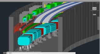
3D Map will help Fermilab install a new beam transport line
The Alignment & Metrology Department maintained a high precision control network throughout the laboratory complex. For the scanning process, a Leica ScanStation P20 ultra-high speed 3D Scanner was used in conjunction with special laser scanner targets, modified to fit within the existing control network points. Exact Metrology’s Leica ScanStation P20 was chosen for its combination of high accuracy and low scan noise, plus its industry-leading environmental specifications for industrial as-built documentation. The software chosen to aid the process was Leica Cyclone, producing TruView—a web-enabled panoramic point viewer allowing the user to view, pan, zoom, measure and mark up point cloud data over the web. Additionally, RSL300 laser scanner target markers from Berntsen International Inc. were mounted concentric to 1.5” radius steel half spheres interfacing with Exact Metrology’s laser tracker nests. The coordinates of the control network, determined at the millimeter level, were provided to Exact Metrology to globally register all scans relative to Fermilab’s system. Thus, the end product provides information for all scanned objects in the common coordinate system used for the entire Fermilab site.
Fermilab has a long-existing relationship with Exact Metrology, having purchased and rented equipment from their instrument pool plus contracted for metrology services as on-site work, such as this scan.
Exact Metrology is an ISO 9001:2008 Certified Company.
 Exact Metrology, with facilities in Cincinnati and Milwaukee and affiliated offices throughout the Midwest, is a comprehensive metrology services provider, offering customers 3D scanning, reverse engineering, quality inspection, product development and 2D drawings. The company also provides turnkey metrology solutions, including equipment sales and lease/rental arrangements.
For more information on this new system, please contact:
EXACT METROLOGY, INC.
11575 Goldcoast Drive
Cincinnati, Ohio 45249
Phone: 513-831-6620
Toll Free: 866-722-2600
www.exactmetrology.com
stevey@exactmetrology.com
Steve Young, President
Or
EXACT METROLOGY, INC.
Dean Solberg
20515 Industry Avenue
Brookfield, WI 53045
Phone: 262-533-0800
Local: 866-722-2600
www.exactmetrology.com
deans@exactmetrology.com
Or
FERMI NATIONAL ACCELERATOR LABORATORY (FERMILAB)
1117 N Washington Ave
Batavia, IL 60510
Phone: 630-840-2787
Horst Friedsam
—
Exact Metrology, with facilities in Cincinnati and Milwaukee and affiliated offices throughout the Midwest, is a comprehensive metrology services provider, offering customers 3D scanning, reverse engineering, quality inspection, product development and 2D drawings. The company also provides turnkey metrology solutions, including equipment sales and lease/rental arrangements.
Siemens at EASTEC 2015
By Bernard and Company
No Comments
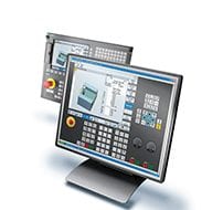 Got a few minutes?
Learn to be a better machinist in 30 minutes or less at Eastec 2015!
Come to Siemens booth #2012 at the show and one of their machining experts will show you how easy it really is!
- Reduce CNC programming, setup and machining times
- Setup a program from a file and prep your offsets
- Provide quick and reliable shopfloor program simulation
- Run an actual part program in real-time
- Use the data to calculate workflow — saving you time
- Avoid machine component collision
- Make yourself a more valuable employee to your shop or production department
- And much more!
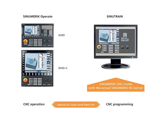
See the difference SINUTRAIN can really make
SINUTRAIN functions exactly the same way as an actual Siemens CNC system. This means you can test all of the operating modes of the graphical user interface step-by-step. Not only is SINUMERIK the top-performing machine tool control in shops worldwide, Siemens also offers training that’s second-to-none. You’ll quickly learn that, with Siemens onboard your machines — anything is possible.
Register to attend EASTEC — compliments of Siemens.
 Simply participate in one of Siemens in-booth demonstrations during the show and you’ll receive your trial version free-of-charge!
Two-Compartment 850°F Universal Oven for Heat Treating
By Bernard and Company
No Comments

979 for heat treating
No. 979 is a 850ºF (454ºC), electrically-heated, universal style oven from Grieve, currently used for various machine shop heat treating operations at the customer’s facility. Workspace dimensions of this oven measure 36” W x 36” D x 36” H in each of the two compartments. 24 kW (12kW per zone) are installed in Incoloy-sheathed tubular elements to heat the dual oven chambers, while a 600 CFM, ½-HP recirculating blower provides front-to-back universal airflow to the workload in each compartment.
This Grieve universal oven features 6” insulated walls, aluminized steel exterior with enamel finish, Type 304 stainless steel interior, double doors, three roller shelves rated for 200 lb. loading, five nickel plated, 100 lb. capacity shelves in the top chamber, three nickel plated, 100 lb. capacity shelves in the bottom chamber and an integral leg stand.
No. 979 controls include a digital indicating temperature controller for each compartment, recirculating blower airflow safety switches, a 10” diameter circular chart recorder for each compartment to record part temperature and manual reset excess temperature controllers with separate contactors.
For more information, please contact:
THE GRIEVE CORPORATION
500 Hart Road
Round Lake, IL 60073-2898
Phone: (847) 546-8225
Fax: (847) 546-9210
Web: www.grievecorp.com
Email: sales@grievecorp.com
Attention: Frank Calabrese, VP
KraussMaffei Berstorff Supplies KRAIBURG TPE with Advanced Extruder Control Technology
By Bernard and Company
No Comments
Co-rotating twin-screw compound extruder used in R&D facility to test material batches, recipes; pre-configured extrusion solution on control package monitors entire machine, providing “big data” for customer at attractive price point

Typical parts made from TPE at Kraiburg
KRAIBURG TPE Corporation in Duluth, Ga. is a manufacturer of custom-made thermoplastic elastomer (TPE) compounds for a variety of market applications in the automotive, medical, general industrial and myriad consumer sectors. At the Duluth facility, the product development department routinely evaluates material batches and new custom compounds for performance and customer specification viability. As an integral step in that process, KRAIBURG TPE engineers utilize sophisticated co-rotating, twin-screw extruder technology provided by KraussMaffei Berstorff, from its facility in Florence, Ky.
Owing to the substantial varieties of color, durometer and the wide-ranging performance properties required at KRAIBURG TPE, monitoring every aspect of the machine performance is critical. This includes all temperatures, speeds, pressures and torque on the extruder itself, plus an underwater pelletizer, gear pump and multiple loss-of-weight feeders used on the line.
At a glance, the operator sees the condition of the machine in real time and can make better on-the-fly adjustments
For the latest machine installed at the KRAIBURG TPE facility, as senior application engineer at KraussMaffei Bertstorff, David Frankenberg, explains, “The lab extrusion line is used for both process and product development assessment. A key requirement was the generation of all data in real time, as part of the management system to be used, as well as the condition monitoring system needed for predictive maintenance strategies being employed.” In cooperation with the KRAIBURG TPE team and after evaluating the competitors for the control scheme, KraussMaffei turned to Siemens for assistance, as this supplier was able to bring a pre-configured and highly cost-effective solution to the requirements on this machine.
Siemens temp zone control system monitors all aspects of extruder, providing “big data” to the host network
As Frankenberg and his electrical engineering associate Martin Gonzalez detailed, the Siemens EXT3370 application package represented a blending of the current PLC technology and drives platform with an HMI capable of providing all graphics and multiple data screens on a single display. In addition, the system had the ability to feed the “big data” directly to the KRAIBURG TPE process data archival & analysis system, where it would reside for real-time and long-range performance evaluation by the product development, quality and process teams. All speeds, pressures, temperatures and other parameters can be instantly assessed, using set point and actual value data on the display, either at the machine HMI or a remote monitor within the KRAIBURG TPE network.
On the KraussMaffei Bertstorff machine, the control system comprises the software solution, Siemens drives and motors, the ability to monitor up to 32 separate temperature zones, touch screen technology on a 15” HMI and scalability on the drives to accept the ancillary equipment being monitored at the KRAIBURG TPE facility. In this way, a truly customized solution was devised using an entirely standard and thus highly cost-effective array of components, according to Frankenberg. As an additional benefit, he noted, the training needed was minimal, owing to the plain language on the control with no need for knowledge of high-level programming skills. Finally, all compound recipes can be easily transferred via USB for portability and security.
Extruder line built by KraussMaffei Berstorff in Florence, Kentucky for Kraiburg TPE
Allen Donn, product development engineer at KRAIBURG TPE, along with his team of engineers and tech specialists, evaluated the installation and commissioning of the machine at the Duluth facility. “The data transfer from the PLC into the same process data archival & analysis system that we use for our other lines at KRAIBURG TPE. A simple Excel file is generated with any parameters desired for analysis, plus we can easily exchange data between R&D and production here. The result is that our ability to utilize production machinery more efficiently has increased substantially with the use of the new KraussMaffei Bertstorff machine in our test department, as the control system gives us real-time hard data we can use to make adjustments on new recipes and entirely new materials.” KRAIBURG TPE performs extensive new compound property performance testing on its TPE formulae and the time compression realized by using the new extruder line in this “real world” R&D operation is providing substantial advantages for the compounder.

Various compounds are formulated at Kraiburg and test run on the KraussMaffei Berstorff extruder at the Kraiburg lab in Duluth, Georgia
KRAIBURG TPE typically runs materials in the 20-80 Shore A hardness range and, as an example, might test out a variety of adhesion grades for over-molding onto polycarbonate, nylon, or other substrates, Donn explained. “When we can pull the data from any machine in the system, adjust it, run it on the R&D machine, and then feed that data back into production, it makes a huge difference in our efficiencies.” In one instance, shortly after the KraussMaffei machine was installed, KRAIBURG TPE engineers were testing 15 compound varieties on the machine very quickly, compared to using production equipment to do that task. “I could look into the software to compare all set point and actual values, remotely, over the entire test period,” Donn noted. He added that the substantial raw material cost savings of more tests, faster results and less waste all contribute to an improved profitability for the company, as well.
For more information on this story, please contact:
KRAIBURG TPE CORPORATION
2625 North Berkeley Lake Road
Duluth, GA 30096
Phone: 678-584-5020
www.KRAIBURG-tpe.com
info-america@KRAIBURG-tpe.com
Attention: Katherine Olano
Or
KRAUSSMAFFEI GROUP USA
7095 Industrial Road
Florence, KY 41042
Phone : 859-283-0200
www.kraussmaffei.com
david.frankenberg@kraussmaffei.com
Attention : David Frankenberg
Or
SIEMENS
Digital Factory
5300 Triangle Parkway
Norcross, GA 30092
Phone : 770-871-3848
www.usa.siemens.com/plastics
mathias.radziwill@siemens.com
Attention : Mathias Radziwill
Regenerative Drive Power Goes Underground
By Bernard and Company
No Comments
Unique below-ground system at Portland Water Bureau utilizes Lucid Energy power generation, Siemens motors and regenerative drives with natural water flow to create energy; will produce 1.1MW of electricity per year, enough to power 150 homes
Recently, the use of regenerative energy has ramped up quickly in American industry due largely to the advancements in drives technology. Through various mechanical components coupled with regenerative drives, energy can be captured or created and used in three ways. Namely, it can be battery-stored for subsequent use, redirected immediately to other electrical power requirements or fed back to the power company in a contract arrangement, all done without loss of host system performance, mechanical component integrity or safety issues.
Typically, regenerative power is produced by, for example, a motor turning during braking or stopping. What if the motor turned as the result of something other than an electrical power supply?
At the City of Portland (Oregon) Water Bureau, they partnered with a local firm, Lucid Energy, who provided a very unique method of power generation. The renewable energy and smart water management solution used is the supplier’s patented LucidPipe™ Power System, which enables industrial, municipal and agricultural water facilities to generate clean, reliable and low-cost energy from gravity-fed water pipeline and stream flow.

The LucidPipe™ Power System uses a unique lift-based, vertical axis spherical turbine technology to smoothly transfer the kinetic energy of the water flow to rotate the motor shaft without impeding the water flow to any great degree. Photo Credit: Sherri Kaven.
For a recent installation under the road at SW 147th Avenue and Powell Boulevard in Portland, Lucid Energy provided their system, which comprises four 42” lift-based turbines spun by the gravity-fed water flow inside the Portland Water Bureau pipeline. These turbines turn four Siemens torque motors as 50kW generators for a 200kW nameplate capacity project. The electricity generated by this system is captured and fed to the Portland General Electric (PGE) grid by four Siemens regenerative drives. In a 20-year power purchase agreement, this project will generate approximately $2 million in renewable energy capacity, to be used for development, installation and operational maintenance costs.
The project investor, Harbourton Alternative Energy, will share the revenue with the City of Portland and Portland Water Bureau to reduce the cost of water operations. Upon completion of the agreement, Portland Water Bureau has the right to purchase the system and the power produced. Since the pipeline is expected to have a lifespan of over 50 years, this project represents a mutually beneficial arrangement for the investor and the city alike.
Known as the Conduit 3 Hydroelectric Project, this system represents the first venture in the U.S. to secure a 20-year Power Purchase Agreement for renewable energy produced by in-pipe hydropower in a municipal water pipeline.
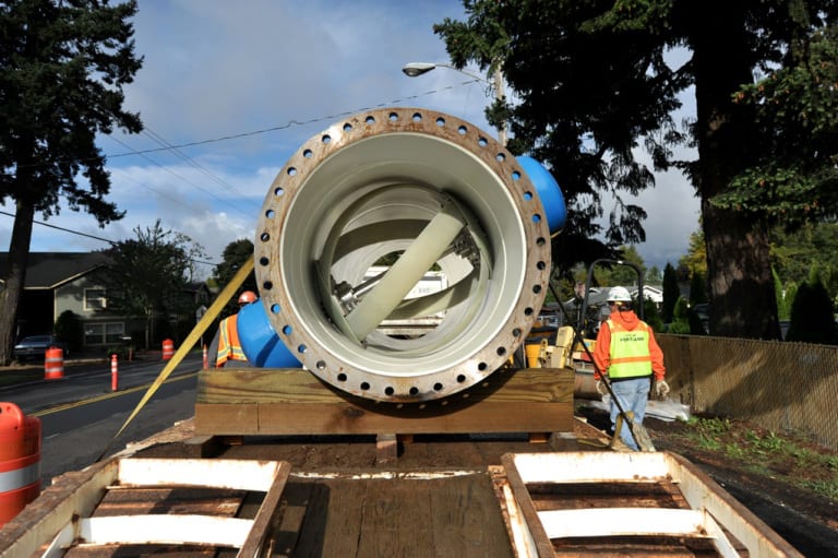
The installation of the system at SW 147th Avenue and Powell in Portland, Oregon. Photo Credit: Sherri Kaven.
“For the execution of this project, we reached out to Siemens, in tandem with their solution partner in our area, Applied Motion Systems, who wrote the software for the regenerative operational protocols, connecting the hardware to the grid,” according to Lucid Energy’s director of operations, Susan Priddy. In addition to the drives and motors on this project, Siemens also provided the motion controller, transformers, circuit breakers and all power supplies. The master control cabinet is installed underground, in close proximity to the pipeline and the four LucidPipe turbines (shown in photo).
Functionally, the water being fed from reservoirs flows downhill to turn the torque motors into generators, which supply power back onto the Siemens Sinamics S120 drive system, which in turn feeds it to the electrical grid of PGE. The electricity is generated by the water flow with no other power source. The pipeline performance is unaffected and there is no environmental impact. The Lucid Energy system has been tested and certified by NSF International to meet the NSF/ANSI Standard 61 for potable water systems. The LucidPipe system extracts very little head pressure, typically 1-5 PSI, so the turbine units can be installed in sequence without disruption of the water flow. The system does not require installation in a pressure-transient zone or where extreme differential pressures are required.
Lucid Energy developed its patented lift-based, vertical axis spherical turbine technology (shown in photo) at the end of the generator’s flange to maximize the use of the water’s gravitational flow to put work back onto the motor. Units can be installed in 24”-96” diameter pipes. For this project, Lucid Energy was able to use standard motor and drive components that would typically require external power supply to control the motion of a machine, as part of its LucidPipe™ power generation system.
Aesthetically, as a collateral benefit, the entire system detailed here is located underground.
The system was final tested in February 2015 and is producing power to full expectations today. Based on subsequent performance metrics analysis, Portland Water Bureau is considering additional installations of the LucidPipe system.
Ryan Misjan and Steve Schoneger from Siemens, plus Susan Priddy from Lucid Energy and Jennifer Allen Newton from Bluehouse Consulting Group contributed to this story.
See the system in action! http://www.lucidenergy.com/how-it-works/
For more information on this story, please contact:
LUCID ENERGY
2420 NE Sandy Boulevard
Suite 203
Portland, OR 97232
Phone: 503-341-0004
www.lucidenergy.com
Attention: Gregg Semler, President & CEO
Or
SIEMENS
Digital Factory
Factory Automation
5300 Triangle Parkway
Norcross, GA 30092
Phone: 770-871-3848
www.usa.siemens.com/drives
Attention: Sandra Tigert
—
How Regenerative Drives Work
Power regeneration is the process of recovering kinetic energy created by a motor turning during stopping or braking or, as in the situation described in this story, by the natural gravitational motion of water flow, and converting that energy to electricity, then feeding it back onto the grid.
Siemens regenerative active infeed drives, as demonstrated in this story, efficiently return the energy created back into the supply system, rather than losing the energy in the form of heat or inertial load losses. The regenerative operation is combined with power quality management, improving the overall operational system efficiency. By virtually eliminating harmonics and optionally providing power factor control to compensate for poor power factor from other loads, active infeed drives provide more stable operation on the load in weak supply systems with voltage and frequency fluctuations and can actually help stabilize the supply system. Motor performance is also improved significantly with active infeed (also called active front end) regenerative drives technology.
“Try Dynapar” Free Trial Offer – Time Sensitive!
By Bernard and Company
No Comments
A “no strings attached” beta test for 30 days from Dynapar
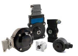
Typical products involved in the TryDynapar campaign; please visit www.dynapar.com/Products_and_Solutions for further results
Gurnee, Illinois – Announced today and effective immediately, Dynapar is offering a free 30-day beta test trial to all interested and qualified parties, for its key product families of incremental and absolute encoders, with thousands of configurations available. According to North American Marketing Director, Ferran Ayala, “This bold program represents our commitment to demonstrating our product quality, engineering expertise and factory support of the Dynapar encoder line to the market at large, with no strings attached.” Ayala further noted the offer would be continued for the foreseeable future.
Three simple steps constitute this offer:
- An end user, OEM or distributor simply configures an absolute or incremental encoder from the TryDynapar assortment of products.
- Dynapar provides the encoder for beta testing for 30 days, at absolutely no cost whatsoever, shipping the product via UPS.
- After the 30-day trial period, the customer has the options to purchase the product or return it to Dynapar, using the instructions provided through a toll-free phone call to the company.
Dynapar encoders are found throughout North American industries, providing motion feedback control. These industries include general factory automation, pulp & paper, primary metals, oil & gas, packaging, beverage, food, pharmaceutical, medical equipment, materials handling, lift & crane, construction operations, off-highway and others, as well as original equipment motor manufacturing.
For more information on this offer, please contact:
DYNAPAR
1675 Delany Road
Gurnee, IL 60031-1282
Phone: 1-800-873-8731
Web: www.dynapar.com/TRYDYNAPAR
Email: inside.sales@dynapar.com
Attention: Ferran Ayala, North American Marketing Director or Heidi Grinde, Product Manager
About Dynapar
Dynapar is a world-leading manufacturer of optical and magnetic encoders and resolvers with more than 50 years of experience in engineering and manufacturing rotary feedback devices. Dynapar was founded in Gurnee, Illinois in 1955 and has been expanded through acquisitions to include Dynapar™, Hengstler™, NorthStar™, Harowe™, and Encoder Technology brand product lines. Dynapar is now uniquely a provider of technologies spanning optical, magnetic, and resolver based feedback.
Pioneering the first true vector-duty hollow-shaft encoder launched Dynapar’s strong presence in several industries, including steel, paper, elevator, oil and gas, wind energy, medical, material handling and industrial servo manufacturing. From small kit encoders to large mill-duty tachometers, Dynapar has the industry covered.
Dynapar customers rely on expertise and support provided from the U.S. sales and manufacturing location in Gurnee, Illinois: Phone +1 800.873.8731 or +1 847.662.2666; FAX +1 847.662.6633; Website: www.dynapar.com. In addition, Dynapar supports global customers with local sales and production locations in Germany, Japan, China, and Brazil.
Continue readingClass 100 Cleanroom Cabinet Oven for Curing Rubber
By Bernard and Company
No Comments
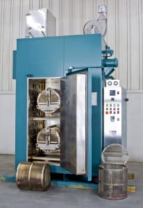
Class 100 cleanroom cabinet oven for curing small rubber pieces | Grieve Corporation
No. 1023 is a 550ºF, electrically-heated, Class 100 cleanroom cabinet oven from Grieve, currently used for curing small rubber pieces in rotating drums at the customer’s facility. Workspace dimensions of this oven measure 26” W x 26” D x 60” H. 36 kW are installed in Incoloy-sheathed tubular elements to heat the oven chamber, while a 2000 CFM, 2-HP recirculating blower provides horizontal airflow to the workload.
This Grieve cleanroom cabinet oven features 6” insulated walls, Type 304, 2B stainless steel interior with ½” inside radius corners and all seams welded, ground and polished, top-mounted heat chamber, two motorized stainless steel shafts cantilevered through the rear wall of the oven with a drum coupling device to rotate the loads, four 18” diameter x 18” deep perforated stainless steel drums with internal stirring paddles and access doors on one end. The oven also contains 24” x 24” x 6” thick HEPA fresh air filters with 2” prefilters and two 24” x 24” x 12” thick stainless steel, high-temperature HEPA recirculating filters.
No. 1023 controls include all safety equipment required for handling flammable solvents, solid state heater control relays, circuit breaker disconnect switch, automatic door switch to shut off the heaters and drum drive when the door is opened, plus a minihelic pressure gauge and validation port across each set of filters on the oven.
For more information, please contact:
THE GRIEVE CORPORATION
500 Hart Road
Round Lake, IL 60073-2898
Phone: (847) 546-8225
Fax: (847) 546-9210
Web: www.grievecorp.com
Email: sales@grievecorp.com
Attention: Frank Calabrese, VP
Triumph Structures – Wichita Machines Wing Spars and Skins on Huge Dual Gantry Mill; Realizes 35 Percent Cycle Time Improvement
By Bernard and Company
No Comments
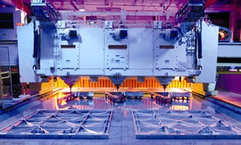
Zimmermann portal milling machine features twin gantries, twin rotary 6-axis milling heads, twin CNCs with completely independent operability to machine parts up to 960 inches in length
Triumph Structures – Wichita, a Triumph Group company, brought a unique challenge to the engineers at Zimmermann (Novi, Michigan) and the solution has yielded various benefits to this major supplier of aerospace components. As Harry Thurmond – President at Triumph Structures – Wichita explains, “We had requirements for spars and stringers that often reached 22’ in length, but we also do a variety of production jobs on smaller sections such as bulkheads. This creates the need for fast, reliable and adaptable machine tools.” In this current mode of manufacturing, Triumph Structures – Wichita considered a variety of options to expand on the capabilities of their existing milling machines, some of which had been in operation for decades.

View down the entire length of the workspace, showing the twin heads and the break wall removed for continuous machining a single workpiece, with co-dependent gantry and CNC operability
Triumph Structures – Wichita specializes in complex, high speed, monolithic precision machining and sub assembly of Aluminum and Titanium structural airframe components often with wall thicknesses down to 0.020 inches. Currently, 21 individual 5-axis machining centers are resident in this facility, with a maximum length of 960 inches. Over 20 other 3-axis and 4-axis machines complete the machining capability for aluminum structures. Triumph Structures – Wichita runs a gamut from build-to-print precision machining of aluminum and hard metal, small-to-large parts, especially aircraft wing spars, Skins, bulkheads, and landing gear components.
While the machine capabilities at Triumph Structures – Wichita were clearly substantial, it was determined that a need existed for a particular machine that could be used to serve multiple purposes. First, the machining of very long parts with volumetric compensation to manage material expansion and the tool tip position over a very long cutting cycle, often multiple days, was required. Triumph Structures – Wichita has extensive experience in this area, given its market focus. However, it was posited that a single machine might also be capable of running multiple smaller parts or operate in twin fashion, occasionally using the entire machine bed with both heads working the same part in tandem. Clearly, the latter scenario would demand extremely close attention to collision avoidance between the gantries, as well as the consistency of surface machining at the points where the twin machining heads intersected.

Zimmermann twin gantry portal milling machine built to suit the special requirements of Triumph Structures in Wichita
For the requirements presented by Triumph Structures – Wichita, the optimal machine necessitated that Zimmermann, a longtime partner and portal machine supplier to Triumph, modify its popular FZ100 machine with twin gantries, each equipped with a three rotary axis head and independent Siemens Sinumerik 840D sl CNC.
As Zimmermann Inc. President Matthias Tockook notes, “We had a variety of machine styles available, but the best solution was a head with three rotary axes, A-B-C integrated in a forked milling head. This provided simultaneous 6-axis cutting in a very compact design, with no pole position, less overall axis rotation, a constant feedrate capability and improved surface quality.”

A unique head design from Zimmermann is based on three rotary axes. Full 6-axis machining is achieved with 125 RMS inside and 32 RMS outside finish
The individual head machining time scenario was further detailed. If the maximum time was achieved using an A- and C-head with infinite C-axis, the alternative A-B-C integrated rotary axis head could accomplish the same work in 25 percent of that time.
In designing the final work envelope and machine structure, Zimmermann engineers determined the best solution was a removable break wall built into the midpoint of the machine bed, which would allow completely independent operation of the entire machine, literally running as two machine tools in one. When removed, the machine bed could accept parts up to 960 inches in length and process them using the twin heads working in tandem and monitored for total collision avoidance by the two CNCs onboard. Owing to the unique volumetric compensation feature of the Siemens CNC, where the execution of the machining is based upon the actual tool tip position, the point of intersection for the twin heads was found to be an easily addressed and resolved issue. Surface integrity on the workpiece would be preserved, while machine and operator safety would remain paramount.
This machine was built over a period of eighteen months. Parts were sent to Zimmerman to be fully tested prior to being erected onsite at Triumph Structures – Wichita.

With doors closed and the break wall installed, photo also shows one of the two Siemens Sinumerik CNC units on the machine. In this setup, each of the two work envelopes of the machine can run simultaneously yet completely independent of the other
In operation, according to Harry Thurmond, the Zimmermann head design provides significant advantages in speed on the typical peaks and pockets found in aerospace structure machining, working in tandem with the look-ahead feature on the CNC. “It slows down and speeds up in anticipation of the next required surface contour. Over long run times, this can translate into an improvement of 35 percent or better, because there is no deburring or polishing required. We routinely get better than a 125 RMS finish on inside pocket surfaces and up to a 32 RMS on the outside of the Series 7000 aluminums we run. Combined with the flexibility of the machine to work a single structure or individual workpieces simultaneously, we have been quite satisfied with the results to date.” On longer runs, Thurmond adds, the chilled coolant used on the Zimmermann is helpful in minimizing thermal expansion of the material, a critical factor in long run machining work here. An added advantage, the machine is used to produce workholding and fixturing devices. Lastly, Harry noted that the Zimmermann machine is equipped with test probes, so it can be used as a CMM to measure workpieces in process.
The 3-axis head avoids the pole position of the traditional 2-axis A-C head at A = 0º. In this Zimmermann head design, the B-axis moves +/- 15º inside a rigid curved guideway for handling the inner sloping and especially the pockets typically found on aero structures, so simultaneous 6-axis machining is achieved with high surface finish integrity.
The new machine at Triumph Structures – Wichita is further equipped with a stationary clamping table, fixed mounted side walls, DemTec composite fill on the base and side walls for enhanced stability and vibration damping. Backlash-free drives on both sides with rack-and-pinion mechanisms are sealed from contamination and guided on both sides. All axes have feed rates to 60m/min and accelerations to 4m/sec2. Each head can access a 60-position toolchanger on the machine.
For communication of data from the machine, Triumph Structures – Wichita integrates the CNCs into their Ethernet network via DNC and hard-wiring. Through a remote monitoring feature on the Sinumerik 840D SL CNC, Zimmermann is also able to maintain awareness of all conditions on the machine in real-time.
At Triumph Structures – Wichita, design to CENIT CAM post-processor operations are done through Vericut simulation at the CAD station.
A unique head design from Zimmermann is based on three rotary axes. Full 6-axis machining is achieved with 125 RMS inside and 32 RMS outside finish
Harry Thurmond notes, “We had grown steadily over the last decades, since our incorporation of 5-axis work in the 1990s, and were ready to jump to a new level of competence for our customers, who represent the top players in both commercial and military aircraft, making Triumph Structures – Wichita a more value-adding supplier. Our part length capability had been 22’ here in Wichita and we were committed to expanding it, to compete in the 40’-80’ part ranges. As with all aerospace structure machining, material removal rates are extremely high. We can start with a 5600 lb. workpiece that ends up at 100 lb., for example.” Harry further noted this means the machines at Triumph Structures – Wichita must be very robust with high-precision control of the cutting cycles, which often run for multiple days.
Commenting on the CNC selection, Matthias Tockook of Zimmermann observed, “With all the challenges we had on this machine, including the axes of motion, the integration of the twin gantry movements, the substantial safety factors involved and the need for independent and also co-dependent gantry operations, we quickly determined that only twin Sinumerik 840D sl CNCs could handle this job.” The machine built for Triumph Structures – Wichita also includes Siemens servo motors and drives plus spindles running at 73kW/95HP and 27,000 rpm in operation.
Triumph Structures – Wichita specializes in complex, high speed, monolithic precision machining and sub assembly of Aluminum and Titanium structural airframe components.
For more information on this story, please contact:
Siemens Industry, Inc.
Drive Technologies — Motion Control (Machine Tool)
390 Kent Avenue
Elk Grove Village, IL 60007
Phone: 847-640-1595
Fax: 847-437-0784
Web: www.usa.siemens.com/cnc
Email: SiemensMTBUMarCom.industry@siemens.com
Attention: John Meyer, Manager, Marketing Communications
Others involved in this story may also be contacted:
Zimmermann Inc. — Portal Milling Machines
24371 Catherine Industrial Drive
Suite 233
Novi, MI 48375
Phone: 248-305-9707
Web: www.zimmermann-inc.com
Email: matthias@zimmermann-in.com
Attention: Matthias Tockook, President
Triumph Structures – Wichita
3258 S. Hoover Rd.
Wichita, KS 67215
Phone: 316-942-0432
Web: www.triumphgroup.com
Email: hthurmond@triumphgroup.com
Harry Thurmond, President
Why Live Tooling for CNC? with Heimatec’s Preben Hansen
By Bernard and Company
No Comments
A brief introduction to the basics of this machine tool method, its concepts and recent developments in the technology
By Preben Hansen, President, Heimatec Inc., Prospect Heights, IL
Live tooling, as the name implies, is specifically driven by the CNC control and the turret of various spindle and powered sub-spindle configurations on CNC lathes to perform various operations while the workpiece remains in orientation to the main spindle. These devices, whether BMT or VDI, are also called driven tools, as opposed to the static tools used during turning operations and are usually customized for the particular machine tool builder’s turret assembly.

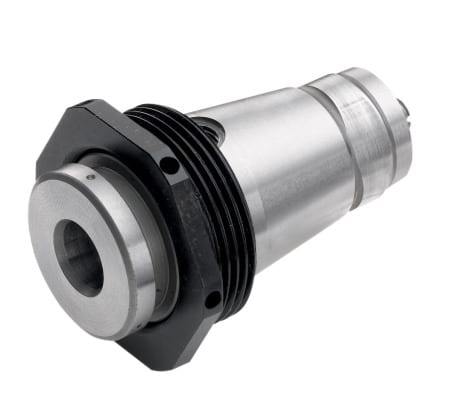
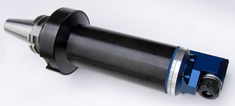
+135º/-30 universal style adjustable tool might be the ideal solution for families of parts
Most often, live tooling is offered in standard straight and 90º configurations with a wide variety of tool output clamping systems, including collet chuck, arbor, Weldon, capto, whistle notch, hydraulic, HSK, CAT, ABS and a variety of custom or proprietary systems developed by the many suppliers to the industry.
As your jobs change or volume increases or you encounter specific challenges in machining very large parts with deep pockets or very small intricate parts, for example, and the need arises for new machinery, a common error is made by accepting the standard tooling packages provided by the builder. This is most definitely not a criticism of the standard packages from builders, but this article is meant to give you a set of parameters to consider when evaluating the tooling and toolholding devices to use in your shop or production department. Simply stated, you need to do as much evaluation of your process, when determining the proper tooling to be used, as you did when you evaluated the various machines available for purchase.
This examination can range from the simple (external vs. internal coolant, for example) to the sublime (adjustable or extended tooling configurations) to the truly exotic, an example of which will end this article.
Tool life is the product of cutting intensity, materials processed, machine stability and, of course, piece parts produced. Two seemingly identical job shops can have vastly different tooling needs because one is automotive and one is medical, or one specializes in the one-offs and low-volume work, while the other has a greater occurrence of longer run jobs. The totality of your operation determines the best tooling for the machines being purchased.
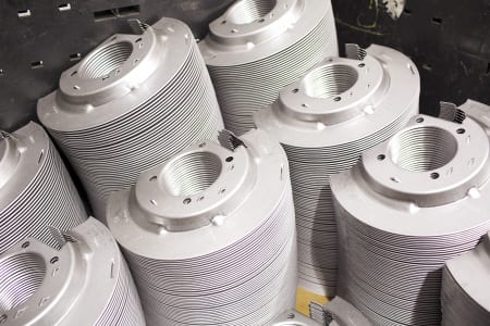
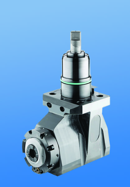
Example of a very large, deep pocket tool that initially seemed too expensive, until the tests proved otherwise
Bearing construction and the resulting spindle concentricity drive the life of any tool and you might find that just a 10-15% greater investment in a better design can yield both longer lasting cutters and consistently superior finish on your products. Of course, the stability and rigidity of the machine tool base are also critical factors, especially on large or deep pocket workpieces, where the distance from the tool base to the cutter tip is greater. Bevel and spur gears that are hardened, ground and lapped in sets are best for smooth transition and minimal runout. Roller bearings are consistently superior to spindle bearings in live tooling applications, so look for a combination system to get the highest precision possible. Also look for an internal vs. external collet nut, so the tool seats more deeply in the tool, as superior rigidity will result.
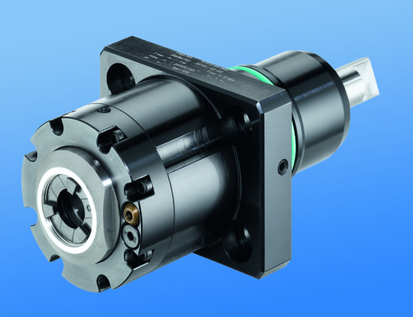
Internal clamping nut seats the tool more deeply
Likewise, coolant high pressure might be desirable. Look for 2000 psi in 90º and 1000 psi minimum in straight tools.
You need to ask another question, namely, is the turret RPM sufficient to handle the work to be done? It’s possible a speed increaser on the tool would be helpful. Would it be beneficial to move secondary operations to your lathe? Gear hobbing can be accomplished or producing squares or flats through the use of polygon machining.
Standard live tooling most often is best suited to production work, where the finish, tolerances and cutter life are critical, while quick-change systems may be better suited to the shop producing families of products and other instances where the tool presetting offline is a key factor in keeping the shop at maximum productivity.
This opens the discussion of long-term flexibility and it’s the most often overlooked consideration in buying live tooling. What work do you have in the shop, what work will be coming in the future and the overall economies of a changeable adapter system on your tooling may be considerations not often made when the focus is centered on the machine being purchased. Dedicated tools for large families of product may be desirable, but consider a changeable adapter system and talk to your supplier before making that determination. Likewise, if the future work you’re bidding involves more families of product, think ahead when buying the initial tooling on the machine.
If standard ER tooling is suitable for the work, there are many good suppliers but do consider the construction aspects noted above. For a quick-change or changeable adapter system, there are fewer suppliers in the market, so seek them out and be sure they can supply the product styles you need for all your lathe brands. Adjustable angle head systems can be costly but very worthwhile, owing to the stability and rigidity of their construction, when producing families of parts with only slight differences in the dimensions.
Now, one of the exotic examples promised earlier…it evidences the value of having test runs done on alternative tool styles…
Internal clamping nut seats the tool more deeply
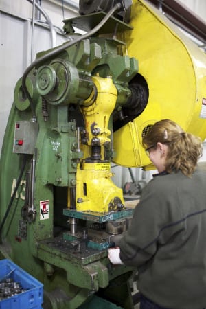
One company was doing a cross-milling application on an AL6063 sheave, using an ER40 output tool on a Eurotech lathe, running 10 ipm at 4000 rpm. They were making three passes, with a cycle time of 262 seconds and getting a chatter finish on 20,000 pieces per year. The annual cost of the machining was over $130,000. By using an improved adapter tool design with ER32AX output and the same parameters, they were able to produce the part in a single pass with a smooth finish and cycle time of just 172 seconds. Over the course of the year, this turned into a savings of $45,000, approximately 20x the cost of the tool. The bottom line is the bottom line, as the accountants tell us.
In the end, you may not need a +135º/-30 universal adjustable tool or a multi-spindle live holder or even a quick-change adapter system, but do consider all the options. Talk to your machine builder and several tool suppliers, plus the most important people in this equation, your shop personnel, as their input is invaluable.
For further information and literature, or to arrange a demo on this new line, please contact:
 Preben Hansen, President
HEIMATEC INC.
16 E. Piper Lane Suite 129
Prospect Heights, IL 60070
Phone: 847-749-0633
Fax: 847-749-2445
Email: info@heimatecinc.com
Website: www.heimatecinc.com
Connect with Heimatec Inc: ![]()
![]()
![]()
![]()
![]()
Upgraded Controls On ESCO Machine Help Reduce Urethane Cutting Production Time From 3½ Hours To 20 Minutes
By Bernard and Company
No Comments
Advanced motors, drives and rapid feedback controls make substantial improvements in machine performance at Grand Rapids supplier to poly foam insulation and padding industries
As Rick Hungerford, president and CEO of Edge-Sweets (ESCO) points out, think of the mattress that remembers, the steering wheel that saves lives or the bandage pad with built-in antibiotic. All these products start from blocks of cast polyurethane foam in various densities, then get cut, profiled or shaped by special machinery. ESCO is a leading manufacturer of such machinery, supplying the furniture, mattress, automotive, packaging, pipe insulation, healthcare and other industries with automated CNC profilers and horizontal cutting machines. Production speeds up to 840 inches per minute (21.33 meters per minute) are achieved on flexible and rebonded polyurethane, latex and viscoelastic materials, when used as either stand-alone cutting machinery or in tandem with automated materials handling and packaging lines. The ESCO end user base reaches into many industries in the global market.
On two recent developments in the company’s machinery line, an engineering evaluation of competing motor, drive and controls lines was conducted, under the direction of Hungerford, who notes, “On our PMIII-1530, a horizontal profile saw with a 1.5 meter x 3 meter block cutting capability, we worked with one of our most trusted local suppliers of automation components, Wes Morgan from Electro-Matic Products, who introduced us to the Siemens motion controller, servomotor, gearmotor and drive package. We were seeking a controls platform that would have global support and standards compliance, as more of our machines are utilized for production outside the U.S. today than at any time in the past.” Hungerford further noted that, while the axes of motion are relatively limited on his company’s machine lines, the high-tension maintained and the need for precise positioning of the cutting wire on this machine made it necessary to have the most accurate and durable motor and drive combinations available onboard.
Rick Hungerford Jr., president and CEO of ESCO (left), inspects the drives cabinet with Wes Morgan of Electro-Matic, the local Grand Rapids supplier of the Siemens product line.
Incorporating the Simotion motion controller, Sinamics low-voltage drives and Simotics S-1FK7 servomotors from Siemens gave ESCO not only the performance levels desired, but also the global application engineering, technical support and parts inventory benefits of this international supplier. “Our machines are in use around the world,” states Hungerford, “and we needed great confidence in our control package supplier’s ability to support the machines and our sales team with parts and service, everywhere in the marketplace. In Siemens, we found such a partner. Plus, their local representative here in Grand Rapids, Electro-Matic, had established a solid relationship with our company and my team.”
Functionally, according to Hungerford, the Siemens package allowed a single, common DC bus without stand-alone drives plus the system provided by Siemens is scalable to allow the cutting machine being interfaced with additional mechanisms and loading/unloading devices as part of an overall automated production line for customers. The PMIII-1530 is operated by a single PC plus a remote operator pendant that allows free movement with full operation control of the machine during setup.
In selecting and programming the proper components for the ESCO machine, Siemens and Electro-Matic Products provided an optimized solution using the Sizer and Simotion Scout software provided by the component manufacturer. Once all the parts are in-house, construction of this machine is typically achieved in approximately 30 days, according to Hungerford, as ESCO does the bulk of the framework and final assembly onsite at the Grand Rapids factory.

The Foamular® industrial pipe insulation produced on the PMIII-1530 is used in the oil and gas industry.
The operation of the machine (as shown in the photos) begins with the CAM programming software written by the ESCO engineering team, plus additional data programs made available through ASTM for pipe and tube configuration. Hungerford mused, “It’s sorta like Etch-A-Sketch, but hardly a toy. Our engineers can take the canned programs and quickly make the necessary adjustments to the cutting paths to suit the machine cutting capabilities and the workpieces our customers are producing.” The software program is vital in accomplishing both an effective cutting as well as optimum utilization of the raw materials, through the nesting of the parts in the master workpiece block, done by the computational algorithms in the program.
The workpiece is then loaded onto the vacuum table, the cutting head is positioned and the process begins. The material used by the ESCO customer, in this case, is Owens Corning Foamular®, a rigid polystyrene prepared in a tongue-and-groove configuration for industrial pipe insulation as the end product.
In operation, the motors, drives and feedback devices work in tandem to ensure a quick, smooth and efficient cutting of the material into the desired shapes.
The customer using the upgraded controls model of this ESCO machine is currently reporting a reduction in its cutting cycle times from 3½ hours to 20 minutes, according to Hungerford.
Commenting further about the drive performance, Wes Morgan of Electro-Matic noted that the Sinamics drive platform offered three distinct benefits. “The product line is consistent across a wide range of motor capacities, which is a real advantage for ESCO. Also, the regenerative feedback feature creates substantial energy savings for the end users, plus the Sinamics drives have a smaller footprint, owing to the dual motor modules and common DC bus system and this results in a more compact control cabinet.” He also noted the Simotion motion controller allows ESCO a single platform to perform simple axis to very complex integrated motion controls with a standard product, resulting in greater efficiencies in the design, programming and installation time for this builder and its customers.
—
On the second machine where ESCO implemented a controls upgrade, the HTX high-tension slitter/stacker incorporates a Simatic PLC, Sinamics variable frequency drives, Simotics servomotors, motor starters and contactors from Siemens. This machine, instead of a cutting wire, utilizes a tangential razor-like blade in a slit-and-retract motion, with the blade articulating on each pass through the material workpiece and then being automatically coated with silicone in the blade housing to maintain cut integrity.
The unit shown in the photographs here is the HTX 51-88 (indicating a 51” high x 88” wide x 132” long cutting zone), making ¼” thick cuts in a poly foam block. The machine is further capable of 1/8” cuts in production, as Hungerford noted. “This machine operates in tandem with other machinery we build, so the conveyor feed mechanism positions the workpiece for the cutting at the first station, then indexes it through the HTX to the next stations, where additional cuts and profilings are performed.
ESCO also produces vertical cutting machines, convoluters, roll splitters, contour cutting machines, metering and dispensing solutions for lab and production use, plus the company supplies fully integrated systems for polyurethane processing, including robots, curing ovens and mold designs to its worldwide customer base.
For more information on this story, please contact:
EDGE-SWEETS COMPANY
ESCO GROUP INC.
2887 Three Mile Road NW
Grand Rapids, MI 49534
Phone: 616-453-5458
Web: www.edge-sweets.com
Email: info@edge-sweets.com
Attention: Rick Hungerford, Jr., President & CEO
or
SIEMENS INDUSTRY, INC.
DIGITAL FACTORY
GENERAL MOTION CONTROL
390 Kent Avenue
Elk Grove Village, IL 60007
Phone: 847-640-1595
Fax: 847-437-0784
Web: www.usa.siemens.com/lv-drives
Email: SiemensMTBUMarCom.industry@siemens.com
Attention: John Meyer, Manager, Marketing Communications
Watch videos of these machines in operation! https://youtu.be/4lpQ22d7niM