
Contact us today:
(847) 934-4500
tdaro@bernardandcompany.com
Contact us today:
(847) 934-4500
tdaro@bernardandcompany.com
PLC, drive and motion-based functionality and architecture
Abstract
There are several architectural strategies that can be considered for web handling drive system controls. Current industrial control platforms permit the web handling controls to be implemented in either a Programmable Logic Controller (PLC) (typically the same as the machine control), directly in the drive system, or through a motion controller.
PLC-based web control has long been a traditional choice for machine builders for a number of reasons. The PLC provides a single platform for both automation and drive control with a centralized control structure. PLC-based systems offer a suitable level of usability, however, they can be limited in high-end performance capability and in their options for process-level programming.
Drive-based control typically offers distributed control architecture, peer-to-peer networks and an increased level of performance due to faster processing times. Graphical engineering tools are common for drive-based systems and are a preferred programming environment due to their ability to visualize and document the web control processes.
Motion controllers offer the highest level of performance and functional flexibility. Their inherent capability of providing position data can help increase web handling performance on several fronts. Motion controllers also permit the line integration of axis motion functionality such as positioning, electronic gearing and cam functionality in the common web controller. They are not limited by memory constraints and typically utilize the full range of programming languages.
This paper will review the merits of these three control architecture options in detail under the criteria of usability, functionality and performance, and also touch on the related topics of drive safety and remote diagnostics.
Overview / criteria
Usability
Usability defines the control system’s ease of use in the areas of engineering, commissioning, and maintenance. The following points apply to each of the control system options, PLC,
drive-based and motion control.
A common engineering tool utilizing a common database for machine and drive control is
recommended. Individual engineering tools for each controller (PLC, drives, etc.) should be
avoided. The engineering and programming connection to the system should be though a
single point with efficient routing to each drive or controller location in the system.
Additionally multi-user editing is an important feature for complex and large projects.
The programming language used for the web control should be considered for usability. The
programming language should be sufficient for implementing the critical tasks, easy-to-use
and understand. We find that the ideal programming language for the web control or drive
processes to be graphical function chart. Web handling control is a process and a graphical
programming editor offers the most efficient method to develop, visualize, support the
process and produce the system documentation.
The engineering platform should offer efficient and common diagnostic and troubleshooting
tools that include integrated online monitoring capability, time and frequency-based trace tools
and a drive axis commissioning control panel.
Control and drive hardware platforms that store programs on removable media are ideal.
The Compact Flash cards permit the easy swapping of hardware without the requirement
of program or parameter file downloading and retain current machine settings.
Download the brochure/PDF HERE.
—
For specific product information and inquiries, call (800) 879-8079 ext. Marketing Communications or send an e-mail to: SiemensMTBUMarCom.industry@siemens.com.
Siemens Industry Sector is the world’s leading supplier of innovative and environmentally friendly products, solutions and services for industrial customers. With end-to-end automation technology and industrial software, solid vertical-market expertise, and technology-based services, the sector enhances its customers’ productivity, efficiency and flexibility. With a global workforce of more than 100,000 employees, the Industry Sector comprises the Industry Automation, Drive Technologies and Customer Services Divisions as well as the Metals Technologies Business Unit. For more information, visit http://www.usa.siemens.com/industry.
The Siemens Drive Technologies Division is the world’s leading supplier of products, systems, applications, solutions and services for the entire drive train, with electrical and mechanical components. Drive Technologies serves all vertical markets in the production and process industries as well as the infrastructure/energy segment. With its products and solutions, the division enables its customers to achieve productivity, energy efficiency and reliability. For more information, visit http://www.usa.siemens.com/drivetechnologies.
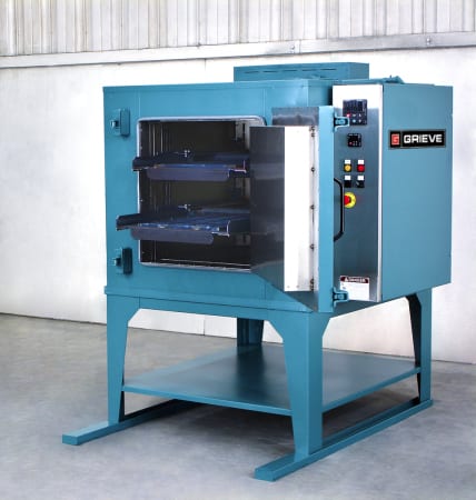
Continue readingNo. 901 is a 1200ºF (649ºC), electrically-heated walk-in oven from Grieve, currently used for heat treating at the customer’s facility. Workspace dimensions of this oven measure 48” W x 60” D x 72” H. 120 kW are installed in Incoloy-sheathed tubular elements to heat the oven chamber, while a 12,500 CFM, 10-HP recirculating blower provides horizontal airflow to the workload. 
This Grieve high-temp walk-in oven features 10” thick insulated walls, comprising 2” of 1900ºF block and 8” of 10 lb/cf density rockwool; inner and outer door gaskets with the inner gasket sealing directly against the door plug, while the outer gasket seals against the front face of the oven; doors equipped with expansion joints on the inner face to guarantee uniform sealing at all temperatures; aluminized steel exterior; Type 304, 2B finish stainless steel interior; 7” insulated floor with truck wheel guide tracks and a 2000 lb. capacity stainless steel shelf oven truck with shelf supports on 6” centers.
Controls on No. 901 include a 325 CFM stainless steel powered forced exhauster with motorized dampers for cooling, manual reset excess temperature controller with separate contactors, recirculating airflow safety switch, 10” diameter circular chart recorder, digital indicating and programming temperature controller and an SCR power controller.
For more information, please contact:
THE GRIEVE CORPORATION
500 Hart Road
Round Lake, IL 60073-2898
Phone: (847) 546-8225
Fax: (847) 546-9210
Web: www.grievecorp.com
Email: sales@grievecorp.com
Attention: Frank Calabrese, VP
 No. 1034 is a 550ºF (287ºC), electrically-heated universal style oven from Grieve, currently used for heating heavy metal dies at the customer’s facility. Workspace dimensions of this oven measure 24” W x 24” D x 24” H. 7 kW are installed in Incoloy-sheathed tubular elements to heat the oven chamber, while a 400 CFM, 1/3-HP recirculating blower provides universal front to rear airflow to the workload.
This Grieve universal oven features 6” insulated walls, aluminized steel exterior, Type 304 stainless steel interior with 2B finish plus two 24” wide x 24” long shelves supported by rollers and each rated at 300 lb. load capacity. An integral oven leg stand is also provided.
No. 1034 controls include a digital indicating temperature controller, manual reset excess temperature controller with separate contactors and recirculating airflow safety switch.
For more information, please contact:
THE GRIEVE CORPORATION
500 Hart Road
Round Lake, IL 60073-2898
Phone: (847) 546-8225
Fax: (847) 546-9210
Web: www.grievecorp.com
Email: sales@grievecorp.com
Attention: Frank Calabrese, VP
Siemens announced today the release of its new single-axis Sinamics V20 AC drive, frame size E, with both Low Overload (LO) and High Overload (HO) ratings. The V20 family features easy setup and operation with excellent cost and energy efficiency. With a power rating ranging from 1/6–40hp at 480V AC, Sinamics V20 drives are available in five frame sizes and are ideal for material handling, conveyor, pump, fan and compressor applications.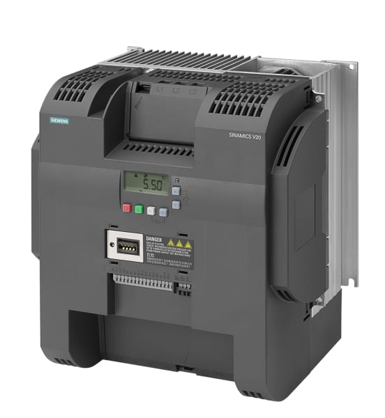
This compact drive can be connected and installed the conventional wall-mounting method or, optionally, mounted with heat sinks pushed through the enclosure wall. Since no additional modules or add-on options are required for operation, installation time is minimized.
The integrated Basic Operator Panel (BOP) enables trouble-free commissioning and operation on-site. Besides the universal serial interfaces that allow for easy connection to Simatic programmable logic controllers (PLCs), a Modbus interface is also included for communication with third-party controls. Pre-built connection and application macros are used for facilitating application-specific settings. For units with power ratings higher than 10hp, a braking resistor can be connected directly to the integrated braking chopper.
Operating the Sinamics V20 drive is just as easy as commissioning. Parameters that have been optimized for one application can easily be transferred to other drive units using SD cards via the Basic Operator Panel or the battery-operated Parameter Loader. The built-in display has the ability to list only those parameters changed from the factory default values rather than having to scroll through all of them.
Tailored inter-connectivity and application macros (i.e. for pumps, fans and compressors) provide the correct settings for the particular application. The Keep Running Mode automatically adapts the V20 drive to the power supply to achieve higher availability when operated on unstable networks. In this mode, line fluctuations are compensated for internally and error messages are acknowledged autonomously. Thanks to enhanced cooling and coated PCBs and electronic components, the Sinamics V20 is extremely rugged, making the unit reliable even in harsh environments.
The demand-driven regulation of the motor speed also provides increased energy savings even for many applications. The Sinamics V20 is equipped with an energy-optimized control mode (ECO-mode) for increased energy efficiency. ECO-mode automatically adapts the magnetic flux in the motor to the optimum operating point. The DC link coupling enables efficient energy utilization of drives grouped together. The Sinamics V20 can also be set to hibernation mode, which prolongs the service life of the motor and also reduces system component wear (i.e. pumps). Additionally, by displaying real-time energy consumption on the operator panel display, the operator always has the drive’s energy and cost efficiencies in focus at all times.
For more information about the Sinamics V20 drive, please visit:
www.usa.siemens.com/sinamics-v20-pr
—
For specific product information and inquiries, call (800) 879-8079
ext. Marketing Communications or send an e-mail to: SiemensMTBUMarCom.industry@siemens.com

979 for heat treating
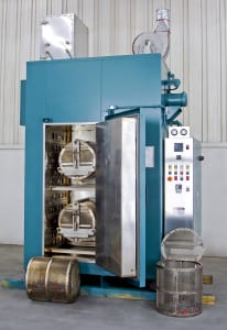
No. 979 is a 850ºF (454ºC), electrically-heated, universal style oven from Grieve, currently used for various machine shop heat treating operations at the customer’s facility. Workspace dimensions of this oven measure 36” W x 36” D x 36” H in each of the two compartments. 24 kW (12kW per zone) are installed in Incoloy-sheathed tubular elements to heat the dual oven chambers, while a 600 CFM, ½-HP recirculating blower provides front-to-back universal airflow to the workload in each compartment.
This Grieve universal oven features 6” insulated walls, aluminized steel exterior with enamel finish, Type 304 stainless steel interior, double doors, three roller shelves rated for 200 lb. loading, five nickel plated, 100 lb. capacity shelves in the top chamber, three nickel plated, 100 lb. capacity shelves in the bottom chamber and an integral leg stand.
No. 979 controls include a digital indicating temperature controller for each compartment, recirculating blower airflow safety switches, a 10” diameter circular chart recorder for each compartment to record part temperature and manual reset excess temperature controllers with separate contactors.
For more information, please contact:
THE GRIEVE CORPORATION
500 Hart Road
Round Lake, IL 60073-2898
Phone: (847) 546-8225
Fax: (847) 546-9210
Web: www.grievecorp.com
Email: sales@grievecorp.com
Attention: Frank Calabrese, VP
Unique below-ground system at Portland Water Bureau utilizes Lucid Energy power generation, Siemens motors and regenerative drives with natural water flow to create energy; will produce 1.1MW of electricity per year, enough to power 150 homes
Recently, the use of regenerative energy has ramped up quickly in American industry due largely to the advancements in drives technology. Through various mechanical components coupled with regenerative drives, energy can be captured or created and used in three ways. Namely, it can be battery-stored for subsequent use, redirected immediately to other electrical power requirements or fed back to the power company in a contract arrangement, all done without loss of host system performance, mechanical component integrity or safety issues.
Typically, regenerative power is produced by, for example, a motor turning during braking or stopping. What if the motor turned as the result of something other than an electrical power supply?
At the City of Portland (Oregon) Water Bureau, they partnered with a local firm, Lucid Energy, who provided a very unique method of power generation. The renewable energy and smart water management solution used is the supplier’s patented LucidPipe™ Power System, which enables industrial, municipal and agricultural water facilities to generate clean, reliable and low-cost energy from gravity-fed water pipeline and stream flow.

The LucidPipe™ Power System uses a unique lift-based, vertical axis spherical turbine technology to smoothly transfer the kinetic energy of the water flow to rotate the motor shaft without impeding the water flow to any great degree. Photo Credit: Sherri Kaven.
For a recent installation under the road at SW 147th Avenue and Powell Boulevard in Portland, Lucid Energy provided their system, which comprises four 42” lift-based turbines spun by the gravity-fed water flow inside the Portland Water Bureau pipeline. These turbines turn four Siemens torque motors as 50kW generators for a 200kW nameplate capacity project. The electricity generated by this system is captured and fed to the Portland General Electric (PGE) grid by four Siemens regenerative drives. In a 20-year power purchase agreement, this project will generate approximately $2 million in renewable energy capacity, to be used for development, installation and operational maintenance costs.
The project investor, Harbourton Alternative Energy, will share the revenue with the City of Portland and Portland Water Bureau to reduce the cost of water operations. Upon completion of the agreement, Portland Water Bureau has the right to purchase the system and the power produced. Since the pipeline is expected to have a lifespan of over 50 years, this project represents a mutually beneficial arrangement for the investor and the city alike.
Known as the Conduit 3 Hydroelectric Project, this system represents the first venture in the U.S. to secure a 20-year Power Purchase Agreement for renewable energy produced by in-pipe hydropower in a municipal water pipeline.
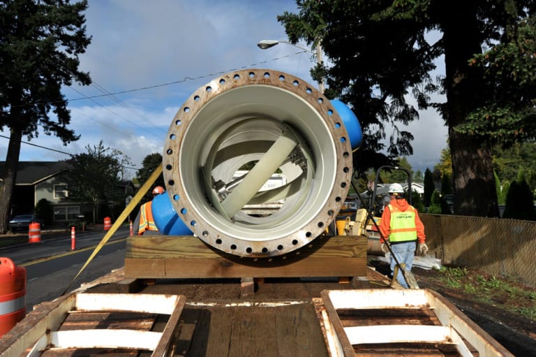
The installation of the system at SW 147th Avenue and Powell in Portland, Oregon. Photo Credit: Sherri Kaven.
“For the execution of this project, we reached out to Siemens, in tandem with their solution partner in our area, Applied Motion Systems, who wrote the software for the regenerative operational protocols, connecting the hardware to the grid,” according to Lucid Energy’s director of operations, Susan Priddy. In addition to the drives and motors on this project, Siemens also provided the motion controller, transformers, circuit breakers and all power supplies. The master control cabinet is installed underground, in close proximity to the pipeline and the four LucidPipe turbines (shown in photo).
Functionally, the water being fed from reservoirs flows downhill to turn the torque motors into generators, which supply power back onto the Siemens Sinamics S120 drive system, which in turn feeds it to the electrical grid of PGE. The electricity is generated by the water flow with no other power source. The pipeline performance is unaffected and there is no environmental impact. The Lucid Energy system has been tested and certified by NSF International to meet the NSF/ANSI Standard 61 for potable water systems. The LucidPipe system extracts very little head pressure, typically 1-5 PSI, so the turbine units can be installed in sequence without disruption of the water flow. The system does not require installation in a pressure-transient zone or where extreme differential pressures are required.
Lucid Energy developed its patented lift-based, vertical axis spherical turbine technology (shown in photo) at the end of the generator’s flange to maximize the use of the water’s gravitational flow to put work back onto the motor. Units can be installed in 24”-96” diameter pipes. For this project, Lucid Energy was able to use standard motor and drive components that would typically require external power supply to control the motion of a machine, as part of its LucidPipe™ power generation system.
Aesthetically, as a collateral benefit, the entire system detailed here is located underground.
The system was final tested in February 2015 and is producing power to full expectations today. Based on subsequent performance metrics analysis, Portland Water Bureau is considering additional installations of the LucidPipe system.
Ryan Misjan and Steve Schoneger from Siemens, plus Susan Priddy from Lucid Energy and Jennifer Allen Newton from Bluehouse Consulting Group contributed to this story.
See the system in action! http://www.lucidenergy.com/how-it-works/
For more information on this story, please contact:
LUCID ENERGY
2420 NE Sandy Boulevard
Suite 203
Portland, OR 97232
Phone: 503-341-0004
www.lucidenergy.com
Attention: Gregg Semler, President & CEO
Or
SIEMENS
Digital Factory
Factory Automation
5300 Triangle Parkway
Norcross, GA 30092
Phone: 770-871-3848
www.usa.siemens.com/drives
Attention: Sandra Tigert
—
How Regenerative Drives Work
Power regeneration is the process of recovering kinetic energy created by a motor turning during stopping or braking or, as in the situation described in this story, by the natural gravitational motion of water flow, and converting that energy to electricity, then feeding it back onto the grid.
Siemens regenerative active infeed drives, as demonstrated in this story, efficiently return the energy created back into the supply system, rather than losing the energy in the form of heat or inertial load losses. The regenerative operation is combined with power quality management, improving the overall operational system efficiency. By virtually eliminating harmonics and optionally providing power factor control to compensate for poor power factor from other loads, active infeed drives provide more stable operation on the load in weak supply systems with voltage and frequency fluctuations and can actually help stabilize the supply system. Motor performance is also improved significantly with active infeed (also called active front end) regenerative drives technology.
Class 100 cleanroom cabinet oven for curing small rubber pieces | Grieve Corporation
No. 1023 is a 550ºF, electrically-heated, Class 100 cleanroom cabinet oven from Grieve, currently used for curing small rubber pieces in rotating drums at the customer’s facility. Workspace dimensions of this oven measure 26” W x 26” D x 60” H. 36 kW are installed in Incoloy-sheathed tubular elements to heat the oven chamber, while a 2000 CFM, 2-HP recirculating blower provides horizontal airflow to the workload.
This Grieve cleanroom cabinet oven features 6” insulated walls, Type 304, 2B stainless steel interior with ½” inside radius corners and all seams welded, ground and polished, top-mounted heat chamber, two motorized stainless steel shafts cantilevered through the rear wall of the oven with a drum coupling device to rotate the loads, four 18” diameter x 18” deep perforated stainless steel drums with internal stirring paddles and access doors on one end. The oven also contains 24” x 24” x 6” thick HEPA fresh air filters with 2” prefilters and two 24” x 24” x 12” thick stainless steel, high-temperature HEPA recirculating filters.
No. 1023 controls include all safety equipment required for handling flammable solvents, solid state heater control relays, circuit breaker disconnect switch, automatic door switch to shut off the heaters and drum drive when the door is opened, plus a minihelic pressure gauge and validation port across each set of filters on the oven.
For more information, please contact:
THE GRIEVE CORPORATION
500 Hart Road
Round Lake, IL 60073-2898
Phone: (847) 546-8225
Fax: (847) 546-9210
Web: www.grievecorp.com
Email: sales@grievecorp.com
Attention: Frank Calabrese, VP
A brief introduction to the basics of this machine tool method, its concepts and recent developments in the technology
By Preben Hansen, President, Heimatec Inc., Prospect Heights, IL
Live tooling, as the name implies, is specifically driven by the CNC control and the turret of various spindle and powered sub-spindle configurations on CNC lathes to perform various operations while the workpiece remains in orientation to the main spindle. These devices, whether BMT or VDI, are also called driven tools, as opposed to the static tools used during turning operations and are usually customized for the particular machine tool builder’s turret assembly.

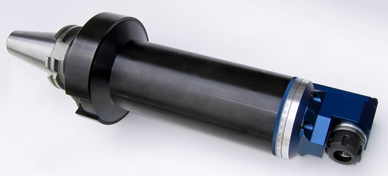
+135º/-30 universal style adjustable tool might be the ideal solution for families of parts
Most often, live tooling is offered in standard straight and 90º configurations with a wide variety of tool output clamping systems, including collet chuck, arbor, Weldon, capto, whistle notch, hydraulic, HSK, CAT, ABS and a variety of custom or proprietary systems developed by the many suppliers to the industry.
As your jobs change or volume increases or you encounter specific challenges in machining very large parts with deep pockets or very small intricate parts, for example, and the need arises for new machinery, a common error is made by accepting the standard tooling packages provided by the builder. This is most definitely not a criticism of the standard packages from builders, but this article is meant to give you a set of parameters to consider when evaluating the tooling and toolholding devices to use in your shop or production department. Simply stated, you need to do as much evaluation of your process, when determining the proper tooling to be used, as you did when you evaluated the various machines available for purchase.
This examination can range from the simple (external vs. internal coolant, for example) to the sublime (adjustable or extended tooling configurations) to the truly exotic, an example of which will end this article.
Tool life is the product of cutting intensity, materials processed, machine stability and, of course, piece parts produced. Two seemingly identical job shops can have vastly different tooling needs because one is automotive and one is medical, or one specializes in the one-offs and low-volume work, while the other has a greater occurrence of longer run jobs. The totality of your operation determines the best tooling for the machines being purchased.
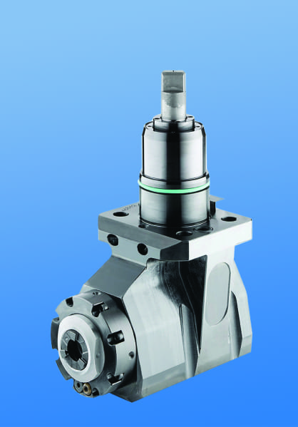
Example of a very large, deep pocket tool that initially seemed too expensive, until the tests proved otherwise
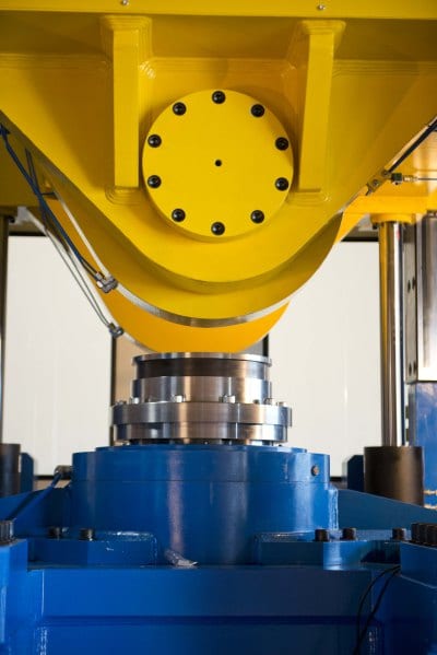
Bearing construction and the resulting spindle concentricity drive the life of any tool and you might find that just a 10-15% greater investment in a better design can yield both longer lasting cutters and consistently superior finish on your products. Of course, the stability and rigidity of the machine tool base are also critical factors, especially on large or deep pocket workpieces, where the distance from the tool base to the cutter tip is greater. Bevel and spur gears that are hardened, ground and lapped in sets are best for smooth transition and minimal runout. Roller bearings are consistently superior to spindle bearings in live tooling applications, so look for a combination system to get the highest precision possible. Also look for an internal vs. external collet nut, so the tool seats more deeply in the tool, as superior rigidity will result.
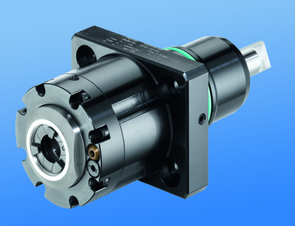
Internal clamping nut seats the tool more deeply
Likewise, coolant high pressure might be desirable. Look for 2000 psi in 90º and 1000 psi minimum in straight tools.
You need to ask another question, namely, is the turret RPM sufficient to handle the work to be done? It’s possible a speed increaser on the tool would be helpful. Would it be beneficial to move secondary operations to your lathe? Gear hobbing can be accomplished or producing squares or flats through the use of polygon machining.
Standard live tooling most often is best suited to production work, where the finish, tolerances and cutter life are critical, while quick-change systems may be better suited to the shop producing families of products and other instances where the tool presetting offline is a key factor in keeping the shop at maximum productivity.
This opens the discussion of long-term flexibility and it’s the most often overlooked consideration in buying live tooling. What work do you have in the shop, what work will be coming in the future and the overall economies of a changeable adapter system on your tooling may be considerations not often made when the focus is centered on the machine being purchased. Dedicated tools for large families of product may be desirable, but consider a changeable adapter system and talk to your supplier before making that determination. Likewise, if the future work you’re bidding involves more families of product, think ahead when buying the initial tooling on the machine.
If standard ER tooling is suitable for the work, there are many good suppliers but do consider the construction aspects noted above. For a quick-change or changeable adapter system, there are fewer suppliers in the market, so seek them out and be sure they can supply the product styles you need for all your lathe brands. Adjustable angle head systems can be costly but very worthwhile, owing to the stability and rigidity of their construction, when producing families of parts with only slight differences in the dimensions.
Now, one of the exotic examples promised earlier…it evidences the value of having test runs done on alternative tool styles…
Internal clamping nut seats the tool more deeply
One company was doing a cross-milling application on an AL6063 sheave, using an ER40 output tool on a Eurotech lathe, running 10 ipm at 4000 rpm. They were making three passes, with a cycle time of 262 seconds and getting a chatter finish on 20,000 pieces per year. The annual cost of the machining was over $130,000. By using an improved adapter tool design with ER32AX output and the same parameters, they were able to produce the part in a single pass with a smooth finish and cycle time of just 172 seconds. Over the course of the year, this turned into a savings of $45,000, approximately 20x the cost of the tool. The bottom line is the bottom line, as the accountants tell us.
In the end, you may not need a +135º/-30 universal adjustable tool or a multi-spindle live holder or even a quick-change adapter system, but do consider all the options. Talk to your machine builder and several tool suppliers, plus the most important people in this equation, your shop personnel, as their input is invaluable.
For further information and literature, or to arrange a demo on this new line, please contact:
 Preben Hansen, President
HEIMATEC INC.
16 E. Piper Lane Suite 129
Prospect Heights, IL 60070
Phone: 847-749-0633
Fax: 847-749-2445
Email: info@heimatecinc.com
Website: www.heimatecinc.com
Connect with Heimatec Inc: ![]()
![]()
![]()
![]()
![]()
For best results in the machining of multiple material layers, cutting parameters must be applied for each different material. The new L-MAX, a portable drilling unit from SOMEX (a member of the SUHNER group of companies) can perform all of these functions in automatic mode.
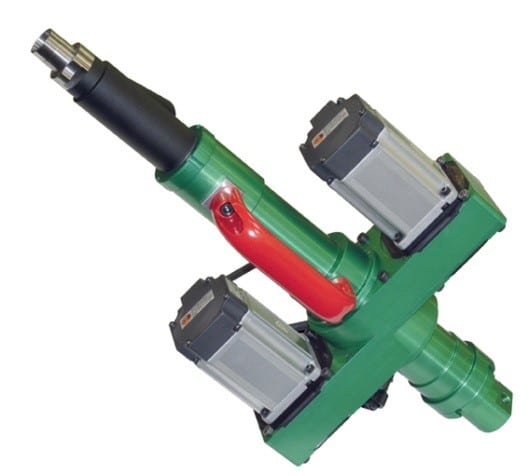
Portable L-MAX drilling unit
Multiple material layers, also referred as Stacks, can be composed of completely different materials, stacked up in layers of, for ex ample: Titanium, Carbon or Aluminum. In order to achieve optimal machining results, each material layer must be programmed with its own cutting parameters- ideally for each layer automatically. The spindle speed and feed rate must be adapted for each material transition to the next.
In the past, aluminum was the primary choice of materials used in the aircraft industry and portable, handheld pneumatic-driven drilling units were used as a common tool in this industry.
The application of these conventional pneumatic drilling units in today’s modern and innovative aircraft industry necessitates extreme compromises. In addition to large air consumption combined with high noise emissions, pneumatic-driven drilling units cannot perform feed and speed variations as required for different stack materials.
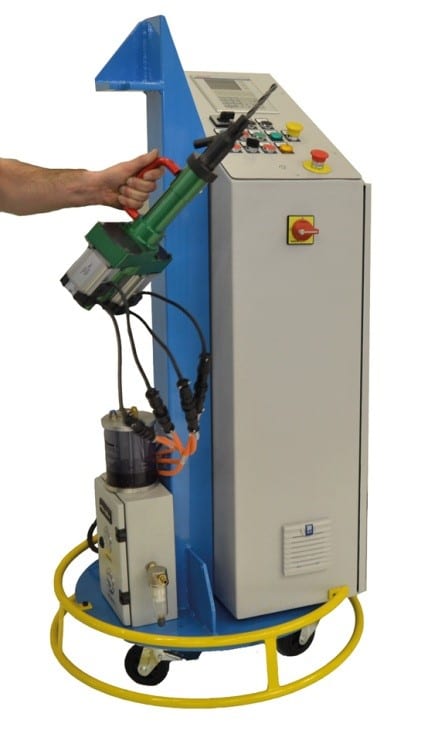
Mobile control system IDM
Consequently, only a portable, handheld NC-programmable drill unit is capable to deliver optimal results and high efficiency, since the aircraft industry imposes rigid quality standards including:
– Concentricity / position between holes ≤ 40 μm
– Surface quality between Ra 1.6 und Ra 3.2
– Circularity / Hole quality for rivets ≤ H8
– Other requirements such as avoidance of delamination.
Working principle for a portable, handheld
NC-programmable L-MAX drilling unit
An L-MAX concept integrates 2 servo motors: The larger motor drives the spindle and the smaller servo regulates the feed. The feed rate is determined by the speed difference between ball screw and ball screw nut or, in other words:
– If the speed (rpm) of the feed servo motor is higher than the spindle motor speed (rpm), then the L-MAX spindle will advance.
– If the speed (rpm) of the feed servo motor is lower than the spindle motor speed (rpm), then the L-MAX spindle will retract.
Both servo motors are controlled by the control system IDM. It allows the user to regulate spindle speed and feed at any position of the total travel.
Furthermore, an adaptive drilling mode can be selected to help improve and optimize a drilling cycle. In this mode, the drill unit recognizes the transition from one layer to the next, automatically. Irregular material thickness of layers at any position are detected and matched with the correct cutting parameters. This way, cycle times can be minimized and machining quality and results optimized.
The control system includes a Minimum Quantity Lubrication (MQL) system, which is directly mounted to the mobile platform.
 Performance data drilling unit L-MAX:
– Programmable spindle speed and spindle feed
– Work cycles such as chip brake cycle and peck feed cycle Spindle speed range from 3,000 rpm up to 5,000 rpm
– Drilling capacity from 4.76 mm (3/16”) up to 11.11 mm (7/16”)
– Integrated Minimum Quantity Lubrication (MQL)
– Light weight, depending on drilling capacity, from 5.5 kg (12lbs)
– Quiet operation up to 65 dBA
– Option: Adaptive drilling mode

SUHNER INDUSTRIAL PRODUCTS, CORP.
Hwy 411 S./Suhner Drive
P.O. Box 1234
Rome, GA 30162
Phone: 706-235-8046
Fax: 706-235-8045
Attention: Lee Coleman, Automation Division
www.suhner.com
automation.usa@suhner.com
Text and pictures files can be found and down loaded at:
www.suhner-press.com
Ann Arbor, Michigan – GMTA (German Machine Tools of America) represents various top-quality German metalworking machine builders, including Wera Profilator, K + G, Pittler, Praewema and WMZ, as well as Arnold lasers. These machines are sold to the North American market exclusively by GMTA, primarily for gear and spline production, as well as other power transmission and various metalworking applications. The company’s target markets include automotive, off-highway, energy and other heavy equipment manufacturing. Machines are provided for gear honing, gear grinding, the patented Scudding® process for gearmaking, polygon milling, turning, gear tooth pointing and multi-task machining operations, as well as various laser operations or laser line integration and parts washing. This newsletter is provided to our friends in the media to keep you and your readers updated on News of Note at GMTA.
In the news…
 -GMTA continues their relationship with Eastern Michigan University (EMU), recently accepting Shannon Lynch, from the Masters in German and International Trade program, as an intern. Shannon’s mentor at GMTA and herself an MBA holder from EMU, the corporate treasurer Claudia Hambleton, remarked, “It’s the first time we’ve ever done anything like this. I feel really strongly about corporate responsibility for young people coming up into the industry…everybody needs experience, but how do you get it? I think this is a really good opportunity for Shannon.” The two shared several German classes at EMU, so the partnership was a natural fit. Shannon is responsible for assisting Claudia with daily office duties including receiving, invoices and translations, in communications with the company’s German partner firms. During her internship, Shannon has also had the opportunity to engage in industry-related educational and technical sessions such as the Economic Forum of the German American Chamber of Commerce, an Advanced Excel Workshop for data analysis and the recent North American International Auto Show Charity Preview, a very prestigious event and a great networking opportunity for the leaders in automotive manufacturing.
-GMTA participated in the annual Auto Show Charity Preview in Detroit and a good time was had by all.
-GMTA is running at “light speed” with their new Arnold laser work cells. Available as single or double work cells, the Arnold systems are offered as CO2 or fiber lasers, with full integration into a machining line, either by means of robotic part articulation or other automated transfer mechanisms, most of which are being supplied to customers by GMTA engineering. Leads from IMTS and the company’s aggressive ad program are already being developed into serious opportunities for the company, often in tandem with other machine tool lines and the Rosink parts washers now offered by GMTA.
-Recently, a Diskus vertical double-disc grinder was sold to Hoergiger Fine Stamping in Canada. The DDS 600 machine feature two vertically arranged motor spindles, each equipped with 600mm grinding wheels used for simultaneous two-sided grinding of shims. The machine has a rotary through-feed system and an integral post-process measuring system, all developed by Diskus engineering and provided to the customer by the GMTA teams from Ann Arbor.
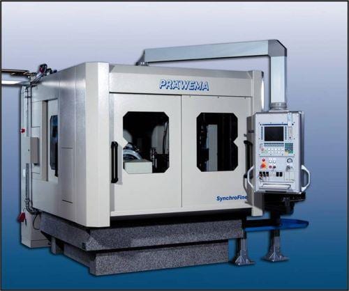
Präwema SynchroFine gear honing machines from GMTA
-The Mexico office of GMTA is reporting brisk activity, owing to the substantial procurement authority in-country now. According to VP Scott Knoy, “This contrasts with bygone days, when the decision-making and purchasing were largely centered in America and specifically in Detroit. It’s a whole new ballgame with the Mexican market today and we believe our new location (Queretaro) there is well positioned to serve this dynamic manufacturing environment.” GMTA already has a substantial installed base of machines in Mexico from all their partner companies.
-GMTA management will be attending EMO in Milan with its partners, then exhibiting at Gear Expo, being held this year in Detroit, October 20-22.
-The alliance with Star, through which GMTA is sourcing tooling locally, continues to prosper and mutually benefit both companies.
-GMTA was featured prominently in a recent article in Manufacturing Engineering magazine, covering the subject of gear making for the energy sector.
-Now available from GMTA, the Präwema SynchroFine 205 HS gear honing machine features direct-driven, digitally controlled spindles for the tool and the workpiece, enabling precise, rigid synchronization. The Präwema Honing gear finishing process produces quality comparable to grinding results for spur and helical gears, as well as shafts. The machine’s software checks the stock allowance and workpiece runout and then optimizes the X-axis approach distance. Measuring the workpiece does not affect the cycle time and the process can reduce overall cycle times by 3 to 5 sec.
For more information on this announcement, please contact:
GMTA (German Machine Tools of America)
4630 Freedom Drive
Ann Arbor, MI 48108
Phone: 734-973-7800
Fax: 734-973-3053
Web: www.gmtamerica.com
Email: scott@gmtamerica.com
Attention: Scott Knoy, VP
Connect with GMTA online: ![]()
![]()
![]()
![]()