
Contact us today:
(847) 934-4500
tdaro@bernardandcompany.com
Contact us today:
(847) 934-4500
tdaro@bernardandcompany.com
 William Allen “Al” Hunter, originator of the matchplate molding machine and mold handling system for sand casting, dies at 89; pioneered many of the techniques and machine concepts used worldwide in the foundry industry
Al Hunter passed peacefully on October 29, 2011 in Naples, Florida. A true giant in the world foundry market, Mr. Hunter changed the way sandcasting was done, by his invention of the matchplate molding and mold handling system in 1964, when he built his first machine, helped by his son and current president of the company, Bill, for sale to Moline Corporation of St. Charles, IL, a malleable iron foundry. He will be missed by all who knew him and appreciated his zest for life and especially his love of invention.
Born on the family farm in Wilkie, Saskatchewan on July 13, 1922, Al left home at 17, took a bus to Edmonton, Alberta and worked in a meat packing plant. In the Spring of 1940, he took a training course in airplane mechanics and then joined the Royal Canadian Air Force at 18.
Married to the late Margaret in Montreal in 1943 and released from military service in 1945, Al moved to Toronto to enter the university there, working as a floor molder at John T. Hepburn Foundry to pay for his part-time schooling.
Three children followed, Bill (current president of Hunter Automated) in 1946, Dianne in 1947 and Linda in 1949. In 1951, Al received his BSME from the University of Toronto and moved back to Montreal to accept a position with Dominion Engineering.
A daughter Heather (wife of current Hunter VP Kevin Purdy) was born in 1956. The following year, Al brought the family to America and accepted a position as chief engineer at Beardsley & Piper in Chicago, a leading builder of machinery for metalcasting and inventors of the SandSlinger technique.
At the end of 1963, Al left B&P to develop his concept for an automatic matchplate molding system. In March of 1964, he founded Hunter Automated Machinery Corporation.
Having run the company day-to-day through 1988, Al turned over the operations to his son Bill, wishing to devote more time to his design and invention activities.
During his tenure at the head of the company, Al formed partnerships and reciprocal agreements with companies worldwide, a tradition that continues today, as Hunter Automated continuously seeks to serve its myriad customer needs for sand handling, testing, molding and finishing operations. Hunter Automated is known worldwide in the foundry industry and its machines are found on every continent.
Al developed various concepts used every day in foundry operations, including multi-level mold handling systems and automatic coresetters. His pioneering, can-do spirit will be missed by all who knew him and admired his total commitment to improving the world foundry market.
He was a member of AFS since 1960, was presented with the society’s Management Service Citation in 1990 and received the foundry industry’s prestigious Grede Award in 2001. He held over 80 patents.
Al will be mourned by his children, their spouses, his 13 grandchildren, 19 great-grandchildren and 1 great-great-grandchild, as well as his family of employees at Hunter Automated, who will carry on his legacy.
The Hunter family asks that interested parties please contribute in Al’s memory to the Foundry Educational Foundation, c/o AFS, 1695 N. Penny Lane, Schaumburg, IL 60173 or at www.fefinc.com.
For more information, please contact:
HUNTER AUTOMATED MACHINERY CORPORATION
2222 Hammond Drive Schaumburg, IL 60196
Phone: (847) 397-5110
Fax: (847) 397-8254
Email: info@hunterfoundry.com
Attention: Bill Hunter, CEO
Web: www.hunterfoundry.com
Connect with Hunter Foundry online: ![]()
![]()
![]()
 No. 857 is an electrically-heated 500°F (~260°C) walk-in oven from Grieve, currently used for annealing plastics at the customer’s facility. Workspace dimensions are 7’ wide x 12’ deep x 7’ high. 100 KW are installed in Incoloy-sheathed tubular heating elements to heat the oven chamber, while a 17,500 CFM, 15 HP recirculating blower provides horizontal airflow to the workload.
The oven has 4” thick insulated walls, plus an aluminized steel interior and exterior. The door sill on this unit was eliminated and both oven doors are equipped with drag seals. Wear bars were also installed on the sides of the workspace for added durability.
Controls onboard No. 857 include a 975 CFM powered forced exhauster and motorized dampers on the intake and exhaust for accelerated cooling of the oven chamber.
For more information, please contact: THE GRIEVE CORPORATION, 500 Hart Road, Round Lake, Illinois 60073-2835 USA. Phone: (847) 546-8225. Fax: (847) 546-9210. Web:www.grievecorp.com. Email: sales@grievecorp.com. Attention: Frank Calabrese.
Continue reading Schaumburg, IL. — SIGMA Plastic Services Inc. has donated SIGMASOFT® polymer process simulation software to Penn State Erie’s School of Engineering at Penn State Erie, The Behrend College, a gift valued at $3.7 million.
With this software, the campus has new technical capabilities for its soon-to-open Medical Plastics Center of Excellence and current Medical Plastics certificate program, two initiatives that address the emerging medical plastics market.
The U.S. market for medical plastics is growing at a rate of 5 percent to 10 percent annually and sales are projected to reach $6.55 billion in 2012.”Thanks to SIGMA Plastic Services, our students and faculty members will be able to develop the next generation of medical devices. This is a great partnership between academia and industry that ultimately benefits our students,” said Ralph Ford, director of the School of Engineering.
The $3.7 million gift supports Penn State Behrend’s goal of raising $32 million during the University’s current capital campaign, For the Future: The Campaign for Penn State Students. To date, the college has secured 81 percent of that goal.
Penn State Behrend’s Medical Plastics Center of Excellence is an applied research and outreach center that supports companies in the development of new medical devices and packaging, technologies that could not exist without advanced plastics materials. SIGMASOFT® software, designed for the molding of advanced elastomer, silicone and thermoplastic materials, supports these technologies.
Students enrolled in the Plastics Engineering Technology bachelor’s degree program can pursue the Medical Plastics certificate. The 14-credit certificate program prepares graduates for careers in medical product development with courses in advanced materials, new product design, manufacturing, and FDA regulatory issues. Nationwide, this is the only medical plastics certificate or degree program offered at the undergraduate level.
“Students will acquire in-depth knowledge of SIGMA products and will be better prepared to put what they have learned into practice after graduation,” said James Chiamardas, president of TPStek. “This is the first gift of SIGMASOFT® to a college or university in the United States. We’re pleased to work with Penn State Behrend on this important initiative.”
 James Chiamardas, a Penn State Erie plastics alumnus and Erie native, played a key role in securing the gift. Chiamardas earned his associate and bachelor’s degrees in Plastics Engineering Technology. He is president of TPStek, LLC, a SIGMASOFT® reseller.
TPStek will provide technical support for the software, which is included in the value of the gift.
Christof Heisser, President of SIGMA Plastic Services, Inc. says, “We are happy to provide the School of Engineering at Penn State Erie, The Behrend College, with 25 seats of SIGMASOFT®, thereby giving students access to state-of-the-art Polymer System Simulation. Simulation has revolutionized the manufacturing world in the last 25 years and has become an integral part of the manufacturing process. It is, therefore, essential to integrate this technology into the education of the next generation of engineers and we at SIGMA are proud that one of the leading universities in the manufacturing world has decided to work with our simulation tool.”
SIGMA Plastics Services is in Schaumburg, IL. Located outside of Chicago, SIGMA Plastics Services Inc. is part of SIGMA Engineering GmbH, headquartered in Aachen, Germany. SIGMA provides 3D Polymer System Simulation software and engineering solutions to companies throughout the world.
For further information on this announcement, interested parties should contact: SIGMA Plastic Services, Inc. 10 N. Martingale Road, Suite 425 Schaumburg, Illinois 60173 USA
Phone: +1 847 969 1001 x 225 Email: cheisser@3dsigma.com Web: www.3dsigma.com Attention: Christof Heisser, President
Agency contact for SIGMA: Wendy McCormick Bernard & Company Palatine, Illinois (Chicago) USA +1 847 934 4500 wendy@bernardandcompany.com
Continue readingHandles parts up to 240” long at major aircraft manufacturer
 Production problems occur in all sizes and trying to meet the challenge of making one size fit all requires a better idea, a better solution.
That is exactly how one customer’s problem became an opportunity for Bertsche. It began as a simple customer request, where a Tier 1 manufacturer of large airplane structural assemblies is required, on a daily basis, to modify semi-finished and partially assembled detail parts. The parts are required for large airplane structural assemblies. Plus, the parts are needed just prior to final assembly and so this manufacturer was searching for an all-purpose machine that could quickly be step up to run a wide variety of parts to support several different airplane programs.
To better appreciate this problem, it helps to understand the difficult work environment.
Airplane manufacturers often start the manufacture of parts for a specific airplane order well before all detail parts for that airplane have been fully defined. This is great for the airlines but complicates the process of building planes to a tight schedule. Furthermore, airplane manufacturers must have considerable flexibility built into their processes, to allow last-minute modification to parts that will be needed shortly thereafter in final assembly.
 In this environment, the manufacturer needs to have the ability, as required, to modify or rework every detail part needed for a specific structural assembly. On short notice, CNC part programs need to be created for virtually every part used in that subassembly, while special tools and fixtures need to be readily available and easily set-up in machines, so that the parts can be manufactured just-in-time before they are needed at assembly. This is truly a “one off” manufacturing environment, where the first part must be a good part with no margin for error.
For Bertsche, the customer’s initial request was simple, namely, replace three small footprint machining centers with a single machine tool that could quickly be reconfigured with tools, workholding fixtures and programs to manufacture the parts needed to complete a specific airplane build (ship) set. Specialized workholding, developed over many years for legacy (older model, mature) airplanes had to fit onto the new machine as well as new workholding needed for the latest model airplanes. Setup time needed to be minutes or, at most, hours and not days.
 The customer wanted to reduce operating costs by reducing the number of people needed to run the machines, reduce setup time and improve the productivity. The existing machines could only manufacture small parts fitting a 20”x30” work envelope, but the new machine had to handle these parts plus parts as long as 240”. There was neither budget nor floor space to replace the existing machining centers with new ones and purchase a new long X-travel machining center.
Having developed a long X-travel, raised-carriage, fixed bed machining center (Xi-Mill) for single or dual work zone long part machining, Bertsche’s solution was to expand the capabilities of the existing machine design by develop a new type of machine, the X-Flex Center, configured with multiple pallet receivers instead of the typical T-slot tables. This allowed the customer to load multiple workholding fixtures into the machine and have them ready to run on short notice. Equipped with a setup changer, the machine could quickly be reconfigured by pulling new workholding fixtures from storage and loading them into the machine to match constantly changing production requirements and schedule changes. Having the dual work zone feature with each work zone having its own dedicated tool changer, the operator was able to load newly tooled fixtures in one zone, while parts were being machined in the other. 
In keeping with lean operating principles, this solution was an FMS that didn’t require all the automation, expense and overhead to manage. The machine was easily overseeable, pragmatic and affordable, plus it allowed the manufacture of a wide range of parts with just a single machine. As the project unfolded, however, many divergent new requirements were identified as desirable and this began to conflict with the original “as concepted” solution.
Long parts, short parts, 4-axis machining, smart fixture control, automatic fixture recognition,
integral thermal growth compensation, video camera actual cutting display, different materials, aluminum, titanium, composite (CFRP) parts, sandwich materials, materials separation, special water filtration, materials separation and other considerations arose, with each requirement mandating additional machine functionality.
 To machine the long parts, the machine needed a two T-slot tables, one for each work zone and the two used together for very long parts up to 240”. It needed a fourth axis trunnion-style table, designed to accept smart fixtures up to 72” in length, fixtures with retractable clamps controlled by the part program. The machine tables needed to be reconfigured from T-slot mode, to 4-axis trunnion mode, to pallet mode and back again.
To meet these requirements, a zero point clamping system was incorporated into the base table, which allowed the pallet receivers to be decked with various long part handling special tables. The zero point clamping features meant that different tables could be quickly installed, with a high degree of repeatability (0.0002” repeatability for a 120” long table). Large and heavy special tables could be craned overhead, lowered into place, clamped and locked down to do production-ready machining in minutes.
For further flexibility, a vacuum workholding system was added to allow any of the pallet receivers to use both mechanical and vacuum workholding.
Each work zone was equipped with a CNC part program addressable connection port, so that special fixtures with complex part clamping (part program actuated) could be controlled by the programmer.
Being a very large machine with two different work zones and machining parts that only 24 hours later were used in final airplane assembly also meant there would be zero tolerance for error or delay. A video camera view port was provided to allow the operator to see what was happening in one work zone, while the other zone was being setup for the next part.
 A further complication revealed itself late in the project. Constantly changing and reconfiguring the worktables with different workholding fixtures also meant that the system was prone to operator error. To address this additional problem, a radio frequency identification system (RFID) read/write station was incorporated into each pallet receiver location. By means of reading the tooled fixture pallet tag, it was now possible to compare the “workholding fixture” installed in a given pallet location to the part program pulled down to the CNC. This insured that the program, part and tool matched. Additionally, the same system was used to scan the tools in the tool changer and could be used to verify the correct tools were available to machine the selected part before the actual machining cycle began.
Switching from aluminum parts to CFRP composite parts required a chip and water filtration system to convey both chips and sludge-like material. The waste material needed to be separated from the coolant. First, the chips from composite sludge, then the coolant suspended CFRP fines had to be filtered from the coolant. Material separation and disposal was not just an operational issue, it was also a facility and hazardous waste disposal issue. The machine was equipped with a flush and wash feature that allowed the entire work zone to be washed down and cleaned before the next material was machined. For chip collection and removal, a conventional chip conveyor was used to transport chips out of the machining area. The chips were separated and put into a dumpster. The cutting fluid carrying liquid and suspended composite particles was pumped to a cyclonic separator, where the sludge was separated and fleece paper filtered for separate disposal.
For long part machining, “hole pattern” to “hole pattern” accuracy was critical and thermal growth of the part relative to the machine was factored into the design. Knowing the temperature of the part (so that appropriate length compensation could be applied) was critical when parts needed to snap together at assembly. To this end, each work zone was equipped with a material sample station. A sample piece of the material was mounted, its temperature measured and the information fed to the CNC for corresponding machining thermal positioning adjustment.
To interface with the shop floor managing network, a front-end PC equipped with bar code reader allowed the operator to scan in work order information and, together with pallet loading instructions, send the right part program for the part(s) to be manufactured as needed to meet daily production requirements. The operator loaded workholding tooled pallets, as directed, to a specific pallet receiver location, while the system verified that the correct tools were available in each tool changer. The operator could then arm (enable) the work zone in which machining was to next take place and wait until the part(s) in the other zone had been manufactured. The process repeated throughout the day with nearly 100 % spindle and operator utilization in a “one off” demand driven environment.
To ensure the correct tools of size and length were being used, each ATC was equipped with its own tool length setter. Each tool could be measured, with offsets adjusted prior to machining. A spindle probe, one for each work zone, allowed fixtures and parts to be probed for location with corresponding work coordinate adjustments. A special marking tool allowed information to be written on a part in easily readable script.
While not every manufacturer has these same complex problems, having such a flexible large machine to make both long and short parts makes sense for even the smallest manufacturer. As a result, any manufacturer who needs flexibility and reconfigurable worktables can quickly adapt his machine tool to meet a wide variety of such machining needs.
For more information contact:
BERTSCHE ENGINEERING CORPORATION 711 Dartmouth Lane Buffalo Grove IL 60089 Phone: (847) 537-8757 www.bertsche.com Attention: Rich Bertsche, President rwb@bertsche.com
Agency contact: Tim Daro Bernard & Company 847-934-4500 tdaro@bernardandcompany.com
Continue reading
Mark Cunningham operates a Gleason gear shaper with Siemens CNC onboard. “It’s very user friendly,” he says.
Using CNC technology on advanced machine tools helps company sell its products worldwide
Roscoe, Illinois is home to many more gear companies than your average town of 10,000 people, but the reason is obvious. During the peak of the machine tool boom in nearby Rockford, it was critical to have these important components made locally. Over the years, that market has changed and so have the gear companies here, each taking its expertise in other directions to offset the decline in local machine tool building.
Forest City Gear Inc. took a different track to remain competitive globally. As Fred Young, CEO of the company, which was founded in 1955 explains, “We decided long ago to do two things. First, to make the very best fine and medium coarse pitch gears in the world, and to do so by using the best machines, people and quality assessment practices possible. Second and just as important, we became committed to reinvesting our company’s profits in newer and better machinery, based on the global standards and the ongoing technical advancements made by machine tool builders around the world.”

Kevin Chatfield has worked on CNC machines for 20 years. Here, he uses a Samputensili gear grinder for internal, external and form grinding. “No other CNC can do all the work the Siemens does.”
This precision gear and spline maker performs nearly every aspect of production in-house, including blanking, turning, hobbing, shaping, milling, gear grinding with form wheels and generating grinding, thread grinding, broaching, honing, straightening, laser marking, magnetic particle inspection, metal-etching, CMM, hardness testing and final surface inspection. Forest City Gear continues to subcontract heat treating and plating. The blanking department, though relatively new, has been expanded several times to keep pace with increasing production. The company boasts nearly every leading brand of gearmaking machine tool on the world market, because, as Young puts it, “We really do put our money where our mouth is, to use that old expression. In a typical year, we invest between 25 and 40 percent of our gross sales back into better gear machines and metrology.”

Brian Turnbull runs various machine tools, including a Hoefler gear grinder, and notes, “The CNC is easy-to-use, very easy to layout and gives me no problems navigating.”
Among the most advanced gearmaking machines in this shop are four Gleason shapers, two Samputensili grinders (form and generating style) plus a Hoefler gear grinder. All these machines have something in common.
At the heart of any machine tool, of course, is the CNC that drives it, controls the motion, detects and integrates all the cutting parameters, feeding back that information to the computer logic of the control to ensure the part being made is as close as possible to the programmed specifications. Meanwhile, the ergonomic or operator-to-machine interaction must always be considered, because a control that’s too difficult to learn and use will result in substantial and costly delays in production. While Forest City Gear has the classic mix of longtime and newer employees, who all bring a variety of computer knowledge and machining skills to the job, this company has consistently sought the most advanced equipment on the market, as part of its “Excellence Without Exception” motto and its practical desire to stay ahead of the competition in the global gear market.

Forest City Gear is among the world leaders in fine and medium pitch gears, selling high-precision applications in medical, aerospace, defense, avionics, instrumentation and performance racing markets.
The control on these machines at Forest City Gear is the Sinumerik 840D from Siemens with specialized gear software. As Young explains, “The extensive gear software developments available are quite remarkable. Most have been a cooperative venture between a machine builder, the CNC builder and folks like us. The result has been software that’s specific to hobbing, shaping, gear grinding and thread grinding.” He also notes features of the Siemens CNC that have yielded positive impacts on the production at Forest City Gear, including “…sophisticated executive software for all machine movements and the fast program reading that allow us to cut and grind much faster, with more options such as reverse direction, segment cutting and combined operations, when compared to other controls we see.”

Company CEO Fred Young notes, “Most of the best gearmaking machines in the world use Siemens CNC and I’ve seen a lot of them, in my time.” He adds the controls have great flexibility, more motion precision and greater diagnostic capabilities than competitive brands he’s used at his company.
Typically, the CNC is used for all axis, rotary and spindle movements and the machine operators particularly appreciate the multiple standard cycles for cutting with degressive feeds, increasing speeds plus special cycles for gear tooth removal and reversing directions to improve finish or reduce cutter wear.
Forest City Gear cuts a wide variety of standard and exotic materials in the production of its gears and splines. These include titanium, Inconel, 4340, 300M, Vascomax 250 and 300, Nitralloy 135M, 9310, 4150, 4140, 8620, aluminum bronze, 13-8, 15-5, 17-4, 316 and 440 stainless, Hastelloy, Ferrium and numerous thermoplastics. The shop can carbide rehob to 60-62 RC and gear grind at all hardnesses.
Kevin Chatfield, a longtime Forest City Gear employee with 20 years’ CNC machine experience, works with the Samputensili grinders and says, “I’ve used all the brands of controls we have here… and for many jobs, no other control can do what the Siemens 840D can do. One example would be the internal, external and form-grinding I do on the Samputensili machine. If the other controls could perform these operations at all, which is doubtful, it would be a very slow process.”
Mark Cunningham, a 12-year veteran of CNC, runs the Gleason machines and notes the controls are very user-friendly. “The screens are easy-to-program and modify, then you get a clear picture of what’s happening at every step in the cycle. The precision is so good, we sometimes need to ‘lie” to the program to get what we want from the machine.”
Brian Turnbull, a newcomer to Forest City Gear, but a longtime machinist, had worked with a competing brand to Siemens CNC and was initially hesitant. “Then, as soon as I saw the easy layout, plus how quickly it could be set-up and go into action, with no trouble navigating at all, I was convinced Siemens was simply a better control.”
Young notes one last point about the CNCs on these machines. “These machine tools produce our most complex parts, including helical splines and internal gears most other shops simply cannot or will not make. The cycle and program read times on the Siemens controls are critical to our production work, plus these are the most expensive machines in the shop, so their run-time cost is the highest.” He adds, “Most of our jobs, though not all, here are short runs on very expensive materials. If the machine takes too long to complete the first part or has repeat rejects, we lose money — it’s that simple. I’m proud to say that neither our operators nor our production supervisors allow that to happen. And the controls on the machines are a big reason why we stay so successful in achieving that accuracy and consistently good part production at Forest City Gear.”
The company has remained among the leaders in the market for high-precision gears, owing to this strategy of buying the best machines, hiring the best gearmakers available and verifying the output of this 100-person shop by using the power of the industry’s leading quality lab, which occupies a cleanroom-level environment in the middle of the factory. As Young explains, “We do checking of our gears and splines at various test stations located throughout the shop, but the final proof resides in our quality lab. Our equipment is so sophisticated, even our competitors often bring us their work to have it checked. It’s one of the things that’s led to our current customer base of about 400 companies, about twenty percent of whom are other gear companies or gear producers themselves.”
For more information on this story, please contact:
FOREST CITY GEAR CO., INC.
Fred Young
CEO
11715 Main Street Roscoe, IL 61073
Toll-Free: 866-623-2168
Phone: 815-623-2168
Fax: 815-623-6620
Web: www.forestcitygear.com
Email: sales@forestcitygear.com
OR
SIEMENS INDUSTRY, INC.
DRIVE TECHNOLOGIES
MOTION CONTROL
MACHINE TOOL BUSINESS
390 Kent Avenue
Elk Grove Village, IL 60007
Phone: 847-640-1595
Fax: 847-437-0784
Web: www.usa.siemens.com/cnc
Email: SiemensMTBUMarCom.sea@siemens.com
Attention: John Meyer, Manager, Marketing Communication
Follow us on Facebook: www.facebook.com/SiemensCNC or Twitter: www.twitter.com/siemens_cnc_us.
—
Siemens Industry Sector is the world’s leading supplier of innovative and environmentally friendly products, solutions and services for industrial customers. With end-to-end automation technology and industrial software, solid vertical-market expertise, and technology-based services, the sector enhances its customers’ productivity, efficiency and flexibility. With a global workforce of more than 100,000 employees, the Industry Sector comprises the Industry Automation, Drive Technologies and Customer Services Divisions as well as the Metals Technologies Business Unit. For more information, visit http://www.usa.siemens.com/industry.
The Siemens Drive Technologies Division is the world’s leading supplier of products, systems, applications, solutions and services for the entire drive train, with electrical and mechanical components. Drive Technologies serves all vertical markets in the production and process industries as well as the infrastructure/energy segment. With its products and solutions, the division enables its customers to achieve productivity, energy efficiency and reliability. For more information, visit http://www.usa.siemens.com/drivetechnologies.
Continue reading ATLANTA — Siemens Industry, Inc. announced today a value-added service for its popular line of 1FK7 servomotors. Using a configurable options menu to build exactly the motor required, customers can now place an order for any Siemens 1FK7 servomotor and have it drop-shipped in three weeks. Thanks to the diverse range of options available, this new service applies to over 100,000 possible configurations. All compact (CT) and high-dynamic (HD) servomotors in the 1FK7 family are included.
With a total of 6150 option pairings and 18 color choices, servomotors in the 1FK7 family can be configured to 110,700 possible designs. Options include stall torque and RPM rating, encoder style and bit resolution, holding brake functionality, shaft style, IP rating, AC line supply voltage and electronic nameplate recognition via Drive-Cliq®. 1FK7 geared motor options are not included in this program presently.
Siemens is now making this service available to customers in the U.S. market. With the motion controller Simotion® and the drive system Sinamics® S stocked in the United States, Siemens is also able to supply complete motion control systems in three weeks’ lead time.
According to Arun Jain, general manager, Siemens Motion Control Business, “We have made the commitment to significantly shorten servomotor delivery times. The 1FK7 family has a wide user base for motion control applications, so we have selected this very important line for our major customer service initiative. We have devised and implemented an entirely new protocol for motor manufacturing and production at our factories.”
For more information, visit www.usa.siemens.com/motioncontrol.
For specific product information and inquiries, call (800) 879-8079 ext. Marketing Communications or send an e-mail to: SiemensMTBUMarCom.industry@siemens.com.
Continue reading
…REDUCES TIME TO PART, IMPROVES PRODUCT PERFORMANCE…WATCH VIDEO, TEST DRIVE AND BUY IT TODAY!
Special introductory price of only $995!
Excel-LentTM software from longtime builder of gears and gearboxes, quickly determines optimum product parameters for various industries; time savings in hundreds of engineering hours being realized. Excel-lent software is on sale through the website.
Please visit www.excel-lentsoftware.com and see a demo of how easy it is to design a new gearbox. The most interesting section to design engineers will be “Design”. With minimal input, the program will calculate the number of teeth in the pinion and gear, DP or Module, face width etc. required to transmit the power, within a few seconds. The calculated data can be exported to the “Analysis” section for complete analysis with clicking the “Transfer Data “ tab on screen. Calculated capacity will be very close to the required power, on the very first try.
Also, the Excel-Lent software’s dimensioning program is the most versatile program available on the market. Non-standard center distance or matching a new gear to an existing gear is as easy as clicking the indicated option. The material tables provided have all the commercially available materials listed, with heat treat and mechanical properties to allow the user to choose any gear material from the list to fit their need.
In all three sections, sample input data are stored for the users to get started. Click on the samples opens the samples table. Clicking one of the samples fills the input screen with data. To run the sample click “Calculate”. We welcome comments and suggestions about our software at any time.
In response to the gear market’s need for optimization software, which has been lacking for many years, Excel-LentTM gear/gearbox design and analysis software has been developed by Excel Gear, Inc. (Roscoe, IL) and written in Visual Basic.Net. This software has been written by engineers who also design and manufacture gears for their own use, according to company president N.K. “Chinn” Chinnusamy.
Mr. Chinnusamy further comments, “Although commercial software has long been available in the gear industry, it has been too expensive or too complicated to be used by engineers without specialized gear design knowledge. Our software is specifically designed with a user-friendly interactive input screen providing defaults and options in accordance with the AGMA 2001 standard (American Gear Manufacturers Association).” The users of Excel-Lent software can easily navigate through the input screens to edit, analyze and produce reports on the optimum gear and gearbox design for various industrial and other applications.
“This software is not designed for any specific industry,” continues Chinnusamy. It can be used for machine tools, heavy materials handling equipment or even the wind turbine industry. For the wind turbine industry, for example, the designer needs a full understanding of all the operating loads on the gear members to arrive at the required power rating.
The key calculations performed are the AGMA power rating and load calculations, including bending strength geometry factor (J) and pitting resistance geometry factors (I). Output from the software is a single page of data printed in a format that is easy to read and interpret. Other commercial software typically prints five or six pages of information, which may be confusing to most design engineers unless they are gear experts, Chinnusamy further observed.
The users of Excel-Lent need not be familiar with AGMA standards to use this software. Those who are not gear engineers can also benefit from the gear engineering knowledge embedded in the software package.
Excel-Lent contains three sections – design, analysis and gear dimensions. Any of the sections can be used individually to run calculations. On a typical job, according to Excel Gear, hundreds of hours typically spent doing the calculations can be saved.
For further information, a test demo, pricing and purchase of this software, please visit www.excel-lentsoftware.com or contact:
EXCEL GEAR, INC. 11865 Main Street Roscoe, IL 61073 Phone: 815-623-3414 Fax: 815-623-3314
Web: www.excelgear.com Email: sales@excelgear.com Attention: N.K. Chinnusamy
ABOUT EXCEL GEAR
Excel Gear brings over 50 years of machine tool experience to the design, manufacturing and quality analysis of its various gear, gearbox, fluid bearing, spindle, CNC gimbal head, nutator and special equipment production. ANSYS software for FEA on stress, strain, deflection, as well as modal analysis, time and frequency domain, our Spindle Analysis Program, MATLAB/Simulink, AutoCAD/SolidWorks/CADAM and other programs are all utilized to affect the best solutions to customer requirements. Excel also builds two-axis CNC gimbal heads with 20,000 RPM motorized spindle, 15,000 RPM cartridge type spindle assemblies and CNC rotary tables for major machine tool companies. Our high-accuracy gear grinding equipment produces to AGMA 15 (DIN 2) tolerances for quality that meets or exceeds the increasing customer demands for high-speed and high power transmission with smooth, quiet operation. Recently, the company has entered the emerging wind turbine market to provide various gears and gearbox components, as well as extensive maintenance and system performance engineering assistance.
PR agency: Tim Daro Bernard & Company 847-934-4500 tdaro@bernardandcompany.com
Continue reading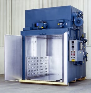 No. 940 is a gas-fired 500°F (~260°C) walk-in oven from Grieve, currently used for curing brake friction materials at the customer’s facility. Workspace dimensions are 72” wide x 96” deep x 78” high. 400,000 BTU/HR are installed in a modulating natural gas burner inside the oven, while 700,000 BTU/HR are installed in a modulating natural gas afterburner. The oven’s initial exhaust passes through the 1400ºF afterburner. A 6000 CFM, 5-HP recirculating blower provides combination airflow to the workload.
The oven has 4” thick insulated walls, aluminized steel interior and exterior, plus a top-mounted heating chamber. All safety equipment required by IRI, FM and NFPA Standard 96 for gas-heated equipment is onboard, including a 650 CFM, ½-HP powered forced exhauster.
Controls on No. 872 include digital indicating temperature controllers and a 10” diameter circular chart recorder.
For more information, please contact:
THE GRIEVE CORPORATION
500 Hart Road
Round Lake, IL 60073-2898
Phone: (847) 546-8225
Fax: (847) 546-9210
Web: www.grievecorp.com
Email: sales@grievecorp.com
Attention: Frank Calabrese, VP
 No. 872 is an electrically-heated 1000°F (~532°C) inert atmosphere oven from Grieve, currently used for annealing copper foil parts. 36 KW are installed in Incoloy sheathed tubular heating elements. Workspace dimensions are 36” wide x 48” deep x 36” high. A 2000 CFM, 2 HP recirculating blower provides universal airflow to the workload.
The oven has 8” thick insulated walls comprised of 2” of 1900°F block and 6” of 10 lb/cf density rockwool, plus an aluminized steel exterior and interior. A structural steel base is provided to raise the roller rails to a 20” loading height. These roller rails, mounted on the bottom of the oven workspace, are rated for 2000 lb. loads.
No. 872 features Grieve inert atmosphere oven construction, which includes a pressure regulator, flow meter, pressure gauge, internal high-temperature gasket, all welded construction in the doorway throat, air jacket on inner oven for cooling, ½” thick cellular silicone rubber atmosphere seal, blower shaft seal, positive latching door hardware, adjustable offset door hinges, outlet with pressure relief, interior seams welded gas-tight and all wall penetrations fitted with compression fittings.
A 975 CFM blower with automatic dampers pulls air through the air jacket on the inner oven for cooling, while the oven’s quick-purge system includes a 1200 SCFH flow meter and solenoid to open the outlet.
Controls onboard No. 872 include a recording and programming temperature recorder and fused disconnect switch.
For more information, please contact: THE GRIEVE CORPORATION, 500 Hart
Road, Round Lake, Illinois 60073-2835 USA. Phone: (847) 546-8225. Fax: (847) 546-
9210. Web: www.grievecorp.com. Email: sales@grievecorp.com. Attention: Frank
Calabrese.
Continue readingSimulation in action: casting quality, realizing innovation, reducing costs
The 1400 °C hot cast iron melt gushes through the gate into the mold. The movement of the flowing metal in the casting rigging and in the gradually filling mold for printing press cylinders and the subsequent solidification process are only chaotic and accidental, at first glance. The engineers of Amstetten Foundry, which forms part of Heidelberger Druckmaschinen AG, are familiar with every detail of the casting system. They ran through the entire process in advance with simulation software. This enables them to predict precisely what the quality and characteristics of the cast iron cylinder will be, when it leaves the mold and is finally integrated in a Heidelberg printing press.
The Amstetten factory is one of the most up-to-date and efficient foundries in all of Europe. It acts as a center of excellence for the manufacture of castings, such as printing press side panels or cylinders, for the entire Heidelberg Group, which has a yearly revenue of three billion euros (~$4.4 billion) and 15,000 employees. The parts are core elements of the sheet-fed offset presses that Heidelberger Druckmaschinen AG, as the market leader, provides to users in the print media industry worldwide. “For our customers, just like for ourselves, the decision for Heidelberg is always a decision for quality,” is how Jürgen Schimmel, Director of Pattern & Casting Engineering describes the company’s vision, which he implements on a daily basis together with the 450 employees involved in casting production. This is because the quality of the individual presses to a significant degree depends on the quality of the castings produced in Amstetten.
Amstetten’s staff does not just produce castings for the Heidelberg Group: 50 external companies order large and small castings in differing batch sizes from the Amstetten foundry. Free market competition does not just make economic sense; it also serves to ensure that all processes are focused on achieving the highest quality, according to Schimmel.
“We have a clearly defined goal: economical casting production with consistently high quality. We see casting as part of an overarching process, beginning in design and finishing in reliably functioning, competitive end products,” Jürgen Schimmel says when formulating the “mission” of the Amstetten foundry. This level of quality is achieved by continuous IT support over the entire production process – from design of the components and patterns to the stable computer controlled melting and pouring processes.
Casting simulation bridges the gap between design and production
The planning department Pattern and Casting Engineering bridges the gap between computer-aided product design and actual production using MAGMASOFT®, the leading software for simulating casting processes. In doing so, the engineers rely on a technology regarded in the industry as one of the most important innovations of the last 50 years. This is because casting process simulation opens up the possibility of taking a look inside the former “black box” of the mold, to understand and predict precisely what happens during pouring and solidification of the melt. As a result, the foundrymen are in a position to accurately characterize the casting and production process as well as predict the casting’s properties before production has begun. What this means in practice is that the engineers are in a position to develop a casting with defined qualities at their computers. Correct production parameters for the casting process, with which the casting can be produced economically and reliably, can be developed with calculable quality. Before simulation technology became available, the individual development steps had to be taken “by hand” – from the part design to its realization as a casting by means of numerous, expensive test castings – and at the end there was still no guarantee that the process would indeed be reliable enough for the casting to be produced in the defined quality.
Save on costs, implement innovations
The foundry of Heidelberger Druckmaschinen AG makes use of simulation technology throughout the entire product and process development process, in order to save materials and costs in a highly price-sensitive market on the one hand, and to drive innovation and optimize component integration on the other.
For example, so-called return scrap is saved by “riserless” casting. Since the melt contracts when it cools, like any material, additional metal usually has to be introduced into the mold via the risers in order to avoid defects / porosity – so-called shrinkage cavities – in the casting. Appropriate design of the casting process reduces return scrap and material consumption. Before making the investment decision for MAGMASOFT®, the foundry had calculated that using simulation return scrap could be reduced by eight percent – which would lower annual material costs by a six-digit euro figure. Additional cost savings accrue from optimization over the entire process. Thanks to the calculated cooling times, it is safe to run production at the fastest possible rate.
For instance, it was possible to greatly reduce shrinkage cavities during the manufacture of a chain guide by reducing riser volumes and altering the gating system. This not only resulted in a significant quality improvement, but also led to a reduction of €15.80 (~$22.75) per part in manufacturing costs, primarily from a reduction of approximately 2.5 kg in return scrap. Given an annual production of approximately 300 pieces, this comes to cost savings of around €4,700 (~$6,768).
Thanks to solidification simulation, it was possible to reduce the number of risers from 5 to 2 together with a 69 kg reduction in return scrap during production of a gear wheel, which lowered manufacturing costs per piece by €31 (~$44.65).
Simulation pioneer as technological partner
As its technology partner for simulation, Heidelberg Foundry relies on a pioneer in this methodology in MAGMA Gießereitechnologie GmbH, Aachen. In the late 1980s, MAGMA transformed casting simulation from university research to practical application. Ever since, the resulting software solution, MAGMASOFT®,® has set technical standards when it comes to simulating casting processes. It simulates mold filling, solidification and cooling during the casting process as well as mechanical properties, residual stresses and distortion of the castings created.
MAGMASOFT® consists of a basis package and a series of additional modules which cover all casting process production steps. They support the user starting from the design of the component, the selection of the melt treatment and casting layout, through pattern design and mold production to final heat treatment and finishing. The MAGMASOFT® application spectrum covers all cast materials, such as gray and ductile cast iron as used at the Heidelberg Foundry as well as aluminum and steel. Every casting process can be simulated with the software in order to design and assess the casting and tooling layouts, cycle times and casting quality.
Simulation software selection criteria
“User-friendly operation, short preparation time until start of calculations, realistic representation of results – those were the leading functional criteria when we chose MAGMASOFT®,” explains Hans Frieß, Director of Planning/Material Management. “And of course, another factor was the potential for future developments in the software.” But it was not just the software’s functionality and quality that were relevant to the decision. MAGMA itself as simulation pioneer was a factor. Hans Frieß puts it like this: “MAGMA established casting process simulation technology as a practical tool. The industry owes its trust in simulation primarily to MAGMA. The associated market and technological leadership and references were also persuasive when we were thinking about introducing a solution.”
Amortization in one year
In the meantime, cooperation in Amstetten with MAGMASOFT® and MAGMA has a track record of about eight years. The investment was amortized within just one year instead of two, as calculated prior to acquisition. The use of the simulation solution has resulted in faster component development, higher component quality and more economic production. The technology has also assisted the foundry in terms of innovation: using MAGMASOFT made it possible to begin manufacturing larger, heavier types of components.
Simulation marketing
The software also plays an important role in marketing and sales. When potential customers inquire about a particular casting, they are not only provided with a price, but also a pledge of reliable component quality and delivery times, based on simulation results. “Thanks to our use of MAGMASOFT®, we have actually acquired customers. When we made the investment decision this effect was one we had neither expected nor taken into account,” Hans Frieß is pleased to note. MAGMA now occupies a correspondingly prominent place in marketing as well: there are numerous casting simulation visualizations on the foundry’s website, shown as recognizable screenshots from the MAGMA software.
Simulation communication
And something else has undergone further development on the basis of the simulation software: communication with the casting designers and the foundry floor. The designers quickly get reliable feedback on whether a new component design is “castable”, while production gets reliable information on how to handle the casting process to achieve the best result. Conversely, based on the documented simulation results, both parties with their expertise can prepare creative solutions, which in turn can then be quickly and easily checked using simulation.
Simulation in the future – knowledge management and service orientation
“Using casting process simulation has now become indispensable for foundries,” Hans Frieß sums up. This was the only way for them to become service providers, taking on design and consultative activities and cooperating more closely with the companies using castings. Moreover, the software protects against know-how loss, since the knowledge is no longer just in the head of an expert but instead stored in a way that can be reused in MAGMASOFT®‘s databases. Consequently, the partnership between foundry and software will intensify further in the time to come – and continue on the basis of a new software generation, which will be launched shortly.
Picture material:
Solidification simulation of a MAGMASOFT®-optimized casting for a Heidelberg printing press (here: gear wheel). Riser optimization produced savings of almost € 40,000 (~$57,600) on this single part.
About software for casting process simulation
Casting process simulation software considers the complete casting process including mold filling, solidification and cooling, and also provides the quantitative prediction of mechanical properties, thermally induced casting stresses and the distortion of cast components. Simulation accurately describes a cast component’s quality upfront before production starts, thus the casting layout can be designed with respect to the required component properties. This results in a reduction in pre-production sampling, but also the precise layout of the complete casting system leads to energy, material and tooling savings for the foundry.
The range of application of MAGMA solutions comprises all cast alloys, from cast iron to aluminum sand casting, permanent mold and die casting up to large steel castings. The software supports the user in component design, the determination of melting practice and casting methodology through to mold making, heat treatment and finishing. This saves costs consequently along the entire casting manufacturing line.
During the last 10 years, the use of casting process simulation has become a valuable business asset for many foundries. MAGMA5 now expands the capabilities of casting process simulation and will further accelerate the acceptance of this technology.
About MAGMA
MAGMA offers comprehensive solutions to the metal casting industry, casting buyers and casting designers worldwide. The MAGMA product and service portfolio includes the powerful modular simulation software MAGMASOFT®,with the newest release MAGMA5, as well as engineering services for casting design and optimization.
Today, MAGMASOFT® is used throughout the metal casting industry, especially for the optimization of cast components in automotive and heavy industry applications.
MAGMA Giessereitechnologie GmbH was founded in 1988 and is headquartered in Aachen, Germany. A global presence and support are guaranteed by offices and subsidiaries in the USA, Singapore, Brazil, Korea, Turkey, India and China. Additionally, more than 30 qualified partners represent MAGMA around the world.
-0-
For more information on this release, please contact:
Christof Heisser
President
MAGMA Foundry Technologies, Inc.
10 N. Martingale Road, Suite 425
Schaumburg, IL 60173
Phone 847-969-1001 ext. 225
Email cheisser@magmasoft.com
Agency contact:
Tim Daro
Bernard & Company
847-934-4500
Continue reading