Contact us today:

(847) 934-4500
tdaro@bernardandcompany.com

Contact us today:
(847) 934-4500
tdaro@bernardandcompany.com
Machining center used at University of Hawaii Institute For Astronomy to produce one-off diffraction gratings for remote sensing instruments used with telescopes and other research instrumentation

University of Hawaii Institute For Astronomy telescopes are able to see the solar system and into deep space with greater clarity than at any other location on the planet, according to Dr. Ritter.
When you enter the laboratories at the University of Hawaii’s Maikalani Institute For Astronomy (IFA) Advanced Technology Research Center on the island of Maui and hear talk of light years, dark energy and space telescopes, it quickly becomes apparent that this is not your typical machine shop. The machining for instrumentation developed here involves some of the most sophisticated techniques on Earth, which is a pun of cosmic irony, as the workpieces produced here are primarily used to help evaluate happenings in deep space.
The Maikalani facility provides laboratory workspace for Physicists and Astronomers performing advanced 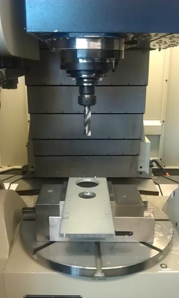
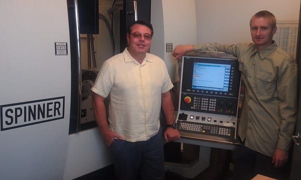
As Ritter explains, “Accuracy is everything in optics. Most of the machining centers I evaluated were in the +/-25 micron (~0.001”) range for accuracy. We settled on a 3+2 axis machine with 100 nanometer precision scales with interferometric remapping on the 840D sl CNC. Because we do experimental fabrication work and optics typically need to be made to micron level tolerances, it was imperative to have a feedback control on the machine tool with a known accuracy and predictable degrees of variation.” As an example, though not suitable for visible light, the optics Ritter discussed required accuracies of a few microns-good enough for infrared optics. Other technologies being developed by Ritter at IFA include novel photonic meta-materials for future space telescopes intended for studying exoplanets and the evolution of our universe.
Dr. Ritter cited the age-old challenge for educational 
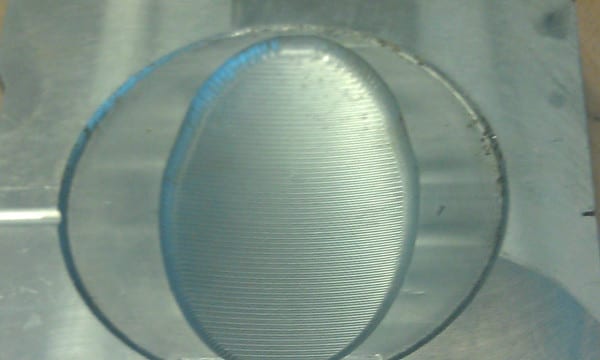
Sample parts produced on Spinner machine, mostly copper and aluminum, include many that become diffraction gratings used on highly sensitive instruments for deep space exploration projects
While invariably the smart guys in any room, Dr. Joe and John Valliant are not machinists by trade, so they were using both Shopmill and CAD/CAM programs like Mastercam with the highly-specialized G-code generator and post-processor needed to create precision path cuts, then running them directly on the mill to quickly begin cutting, an absolute necessity in their one-off world of custom parts.
“For some optics, the millions of coordinates we use for every workpiece are pushing the control to the limit, but it responds well. Plus, the teach-in functionality of the Sinumerik 840D sl CNC and its software package keep us running very efficiently,” according to Valliant, who worked in the lab as a University of Hawaii-Maui college student and has learned CNC machining on the go. In an environment where 0.1 of a wavelength of light is the desired target for accuracy, this is no small achievement. Valliant adds, “Once you’re comfortable with this machine and the control, the process is very intuitive.”
Dr. Ritter, who is constantly pushing the boundaries on novel orbital space telescope designs, notes that the state of Hawaii and the island of Maui in particular have some of the best conditions on Earth for nighttime telescopic observation, as well as the best in the world for daytime solar viewing. The National Science Foundation will soon build the world’s largest solar telescope on Maui. Maui is a little known hotbed of technology development. In addition to solar research and deep space observations, the Institute for Astronomy partners with many nations to push the boundaries of human knowledge, while training future scientists.

Mac McPherson, the Spinner machine dealer and importer for North America, adds, “We do 
“Na Kilo Hoku” means “the watchers of the stars” and the instrument components made here certainly help them do just that — and also gain knowledge from the cosmos for us all.
For more information on this story, please contact:
Joe Ritter, Ph.D
Physicist and Lab Director
University of Hawaii Institute For Astronomy
Maikalani Advanced Technology Research Center
34 Ohia Ku St.
Pukalani, HI 96768
Phone: 808-573-9521
Web: www.ifa.hawaii.edu
Or
Robert McPherson
MacHill Machinery Solutions, LLC
(dealer for Spinner machines)
2245 C-132 Ashley Crossing Drive
Charleston, SC 29445
Phone: 843-873-6888
Web: www.machillmachinery.com
Or
SIEMENS INDUSTRY, INC.
DRIVE TECHNOLOGIES
MOTION CONTROL
MACHINE TOOL BUSINESS
390 Kent Avenue
Elk Grove Village, IL 60007
Phone: 847-640-1595
Fax: 847-437-0784
Web: www.usa.siemens.com/cnc
Email: SiemensMTBUMarCom.sea@siemens.com
Attention: John Meyer, Manager, Marketing Communication
Follow us on Facebook: www.facebook.com/SiemensCNC or Twitter: www.twitter.com/siemens_cnc_us.
—
Siemens Industry Sector is the world’s leading supplier of innovative and environmentally friendly products, solutions and services for industrial customers. With end-to-end automation technology and industrial software, solid vertical-market expertise, and technology-based services, the sector enhances its customers’ productivity, efficiency and flexibility. With a global workforce of more than 100,000 employees, the Industry Sector comprises the Industry Automation, Drive Technologies and Customer Services Divisions as well as the Metals Technologies Business Unit. For more information, visit http://www.usa.siemens.com/industry.
The Siemens Drive Technologies Division is the world’s leading supplier of products, systems, applications, solutions and services for the entire drive train, with electrical and mechanical components. Drive Technologies serves all vertical markets in the production and process industries as well as the infrastructure/energy segment. With its products and solutions, the division enables its customers to achieve productivity, energy efficiency and reliability. For more information, visit http://www.usa.siemens.com/drivetechnologies.
Continue readingWisconsin foundry adding value to parts produced
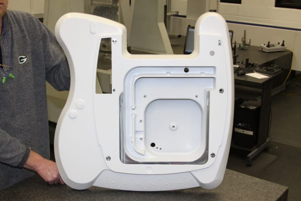 Watry Industries LLC, a large permanent mold aluminum foundry located in Sheboygan, Wisconsin, takes pride in working closely with its customers to co-develop and optimize casting design. In addition to offering casting design assistance and permanent mold casting production in its 172,000 square foot facility, Watry also performs heat treating, precision machining, powder coating and assembly operations in-house.
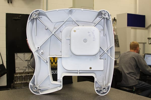 Watry worked closely with its customer to assist in the design process for this part, as well as two other castings used on the same program, from concept through tooling and into production. Several other production processes were considered for making this part, including injection molded plastic, structural foam, plastic cowling over steel fabrication and several casting processes including sand cast, permanent mold and high pressure die cast. After investigation, mechanical strength concerns eliminated some of the plastic construction methods and a thorough cost analysis eliminated the fabrication options as being too expensive. Aluminum castings had a proven track record in similar applications, and a cost analysis was done to compare the various cast processes. Based on the combination of part cost and tooling cost (total cost of ownership) the result of all these studies was that permanent mold was selected as the best process for the application.
Dale Christel
Sales Manager
Watry Industries LLC
3312 Lakeshore Drive
Sheboygan, WI 53081
Office: 1-920-457-4886
www.watry.com
dchristel@watry.com
Connect with Watry Industries online:
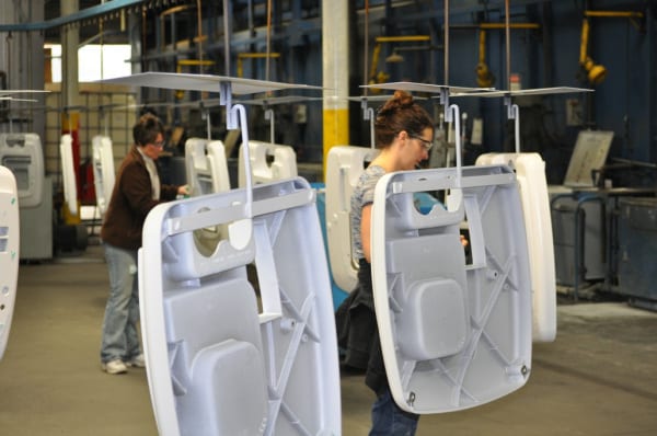
Experts at the nuances of powder coating parts produced in all metalcasting processes, as well as powder application on stampings, extrusions, weldments and assemblies, Watry is able to provide their services on castings made by other processes as well as steel, iron and various alloys.
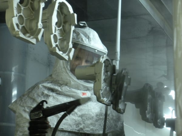
Watry is capable of masking features before painting as well as blowing off un-cured powder in areas where masking is not practical. The Nordson Cyclo-Kinetic reclaim booth, utilizing both manual and automatic guns, is capable of applying the most demanding and high temperature powders, reaching the most difficult areas on any workpiece. In addition, reclaiming the powder that does not adhere to the part during the application process helps control overall costs.
Watry’s roof mounted cure oven, encompassing over 250 feet of conveyor track and operating at temperatures up to 500º F, can cure powder on the largest and heaviest parts at very high line speeds, providing another cost-controlling feature.
Strict quality control systems and procedures include film thickness checks, adhesion testing, color verification and paint hardness testing to ensure compliance to customers’ most demanding requirements.
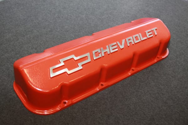
To watch a video on the Watry powder coating operation, please visit http://www.watry.com/video_library.html
For more information on this release, please contact:
Dale Christel
Sales Manager
Watry Industries LLC
3312 Lakeshore Drive
Sheboygan, WI 53081
Office: 1-920-457-4886
www.watry.com
dchristel@watry.com
Connect with Watry Industries online:

This Grieve cabinet oven features 6” insulated walls and Type 430 stainless steel interior, all-welded construction plus explosion-venting latches on the heavy-duty door.
Controls on No. 858 include a digital programming and recording temperature controller, manual reset excess temperature controller with separate contactors and recirculating blower air flow safety switch.
For more information, please contact:
THE GRIEVE CORPORATION, 500 Hart
Road, Round Lake, Illinois 60073-2835 USA. Phone: (847) 546-8225. Fax: (847) 546-
9210. Web: www.grievecorp.com. Email: sales@grievecorp.com. Attention: Frank
Calabrese.
Continue reading
The background of Banner’s industry-leading quality assurance program and supply chain management solution includes many and varied factors. Each individually could provide justification for a major initiative on the part of a responsible, forward-thinking supplier. Collectively, these reasons make an inarguable case for new, stronger management of the supply chain.
Let’s review the reasons why Banner has so vigorously engaged in the industry’s leading quality assurance program.
Reason #1: Because the supply chain needs help
The medical device industry has witnessed a series of costly and dangerous failures resulting from the dilution of device manufacturer standards down the supply chain. The buyer of materials must indeed beware of superficial quality measures and undocumented changes.
An approach that emphasizes prevention represents a viable solution. By investing in supplier relationships premised on stringent purchasing controls, the device manufacturer considerably diminishes the likelihood of a hugely expensive failure and recall with liability. The 1:10:100 rule holds that a dollar spent on prevention of a quality problem forestalls the expenditure of $10 on correction or $100 to rectify a failure.
In Japan and Germany, single sourcing is common and relationships can be decades long; suppliers are considered an extension of the customer company’s operation. American firms have historically not taken this approach. So, American device manufacturers generally work with approved supplier lists that have grown large and consequently difficult to manage.
In the past, device manufacturers commonly worked with multiple suppliers for the same material, to minimize the possibility of a supply shortage or to bring down material price through competition. Today, short-term cost savings are used to justify the multiple-supplier, purchase-order-to-purchase order method. Such near-term savings, however, come with a high potential price: failures that can literally put a device manufacturer out of business. In recent years, thoughtful device manufacturers have concluded that they possess minimal leverage in applying controls to metal melt sources. More than 95% of a typical melt source’s business is outside the medical industry; the melt sources have little incentive to change. Furthermore, device manufacturers often do not buy directly from the melt sources and lacked direct access and contact.
In dealing with suppliers, it is critical that a device manufacturer know how the supplier’s systems have evolved, as did Banner’s, in response to medical device industry needs. Additionally, procedures used to determine acceptability of suppliers must be unambiguous. The ASL should itemize specific products and processes for which the supplier is approved, not just the name of the company. A supplier that has been approved for one product or process should never be assumed to be approved for everything.
Purchasing controls can take many directions in the effort to achieve greater stringency. One promising approach is for device manufacturers to focus on building strategic partnerships with suppliers with the demonstrated capability to provide acceptable product.
Reason #2: Because we’ve got the data
In a time frame coinciding with several high-profile and catastrophic materials problems in the medical device industry, Banner proactively validated all its medical equipment and processes (IQ, OQ & PQ) per FDA protocols. Furthermore, we developed proprietary and particularly stringent bullet-proofing systems to ensure risk mitigation.
Banner designed experiments to determine “worst case” scenarios and effects of processing parameters on the finished metals regarding mechanical properties and surface conditions for static and dynamic or high stress applications. Selection criteria for implant and device grades metals were based on 1) difficulty for machining, i.e. chemistry, 2) difficulty to straightening, i.e. very high mechanical properties, and 3) best commonly used coolants ~ Straight Sulfurized oils vs. water soluble coolants.
We determined that softer material such as aluminum, brass, and carbon steel shrink as much as 0.002” on several passes during straightening; meanwhile stainless, CCM and titanium had minimum deflection. Grades such as Inconel, CCM, 440, 304, and Titanium proved very difficult to turn or grind. The experiment selected 316, Ti, 17-4A, 17-4H900, 440A and CCM grades based on their status of “most difficult” to machine and because of their extensive use in medical devices and implants (SS, CCM and Ti families). Banner chose minimum and maximum sizes of 0.0250” and 1.000” (based on volume/history) on existing equipment.
For a worst-case scenario on straightening, grinding, and turning processes, bars were processed outside validated parameters. Then the supplier removed 125 percent of the routing parameter; for example, if the router states 0.010” removal, Banner tried to remove 0.0125” per grinding pass. Banner also ground samples down to 15 percent of the original diameter by volume. Samples were taken for analysis on surface condition, mechanical properties, and straightness (TIR).
Extensive and detailed protocols determined the effectiveness of equipment function, operations and processes, outputs and revalidation criteria. Hundreds of samples were sent to a 3rd party A2LA and NADCAP (Exova) accredited laboratory for analysis. Multiple samples for each scenario were run and analyzed for repeatability and reproducibility.
The tests concluded that, operating within validated procedures and processes, Banner could produce material that was compliant in terms of mechanical properties without adverse effect on the raw material. Removing 85 percent volume of stock and straightening 20 times has no negative impact on physical properties and surface conditions, as long as validated processing parameters are followed. Operating outside of the safe zone of validated protocols, processes, and parameters, Banner found adverse impacts on final produced materials.
|
Titanium Eli Annealed ASTM F136 Verified by 3rd Party Lab. (Exova) |
||||||||
|
Sample # |
Start Size |
Test Size |
0.20%YS |
UTS |
%EL |
%RA |
Cracks observed at 400x |
|
|
1 |
Ø .750″ |
Ø .251″ |
137,000 |
145,500 |
17.0 |
50.8 |
No |
|
|
2 |
Ø .750″ |
Ø .252″ |
142,000 |
149,200 |
17.0 |
51.8 |
No |
|
|
3 |
Ø .750″ |
Ø .253″ |
137,200 |
147,000 |
18.0 |
50.5 |
Yes |
|
|
4 |
Ø .750″ |
Ø .254″ |
139,200 |
148,200 |
17.0 |
48.7 |
Yes |
|
| Sample # | ||||||||
|
1 |
Material tested as received from mill | |||||||
|
2 |
Material tested as received from mill | |||||||
|
3 |
Processed outside validated parameters | |||||||
|
4 |
Processed outside validated parameters | |||||||
|
3 Point Fatigue Test Cycle Counts |
||||||||
|
Sample # |
Start Size |
Test Size |
Frequency |
Min |
Max |
~ Min |
~ Max |
Cycles to Failure |
|
1 |
Ø .750″ |
Ø .750″ |
15 |
-500 |
-5,000 |
-0.020 |
-0.105 |
16,823 |
|
2 |
Ø .750″ |
Ø .750″ |
15 |
-500 |
-5,000 |
-0.020 |
-0.105 |
15,334 |
|
3 |
Ø .750″ |
Ø .750″ |
15 |
-500 |
-5,000 |
-0.020 |
-0.105 |
13,686 |
|
4 |
Ø .750″ |
Ø .750″ |
15 |
-500 |
-5,000 |
-0.025 |
-0.120 |
4,931 |
|
5 |
Ø .750″ |
Ø .750″ |
15 |
-500 |
-5,000 |
-0.025 |
-0.120 |
3,012 |
|
6 |
Ø .750″ |
Ø .750″ |
15 |
-500 |
-5,000 |
-0.025 |
-0.120 |
3,314 |
| Sample # | ||||||||
|
1 |
Normal straighten and grind using validated processes | |||||||
|
2 |
Normal straighten and grind using validated processes | |||||||
|
3 |
Normal straighten and grind using validated processes | |||||||
|
4 |
Processed outside validated parameters | |||||||
|
5 |
Processed outside validated parameters | |||||||
|
6 |
Processed outside validated parameters | |||||||
For example, per the test performed on implantable grade Titanium ELI ASTM F136, 0.750” diameter bar results showed that excessive straightening could induce surface cracks. Although there was no significant change in the physical properties before and after the test, under dynamic loading (Fatigue Test), the Fatigue cycles were reduced by a factor of 5 when operating outside of highly controlled and proven processes. Application life under validated processes averaged about 15,000 cycles but failure occurred within 20 percent of that application life, at about 3,500 cycles, with processes outside these parameters.
For Banner, an 18-month investment in design of experiment and collection of substantial data and documentation proved most valuable. The findings provided incontrovertible evidence of the need for validated procedures and processes. For Banner customers, the data offer an assurance of quality.
Reason #3: Because the FDA says so
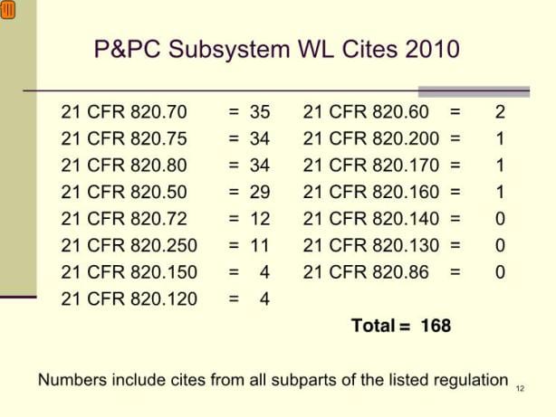
The supply chain stands to receive unprecedented FDA scrutiny in today’s medical device industry. For the FDA, supplier controls represent a top Quality Hot Topic. Specifically, raw materials are increasingly a cause for concern. More than one-third of all 2010 Production and Process Controls (P&PC) subsystem warning letter cites are associated with regulation of material purchasing controls and acceptance activities (Section 820.50 and 820.80). The FDA continues to add dozens of new field inspectors and contracts with yet more inspectors to increase the agency’s capacity to review purchasing controls and acceptance activities, as well as other quality system matters. This activity included the hiring of more than 700 inspectors to ensure adequate, timely inspections overseas. The medical device industry cannot afford to pay less attention to quality topics than the FDA.
Working within the comprehensive parameters set by the FDA, the medical device industry needs to manage its supply chain with unprecedented vigilance. Device manufacturers must take responsibility for the condition and quality of items purchased. It is imperative to identify and mitigate risks in the supply chain. Purchase decisions for devices, raw materials and services must be made with consideration to risk-based principles. Poor purchasing decisions lead to circumstances where companies will not meet regulatory or quality requirements, and will be subject to damage to their reputation and potential litigation. Conversely, purchasing decisions made with attention to the unique risks and needs of the medical device supply chain are imperative.
A strategic change in action
Banner has already employed its new approach and controls in a relationship with an important customer, with mutual benefits and recognized success. The device manufacturer revised specifications to require melt source and melt process validation, independent test lab verification, and an approved supplier list of melt sources. Every raw material lot was subject to certificate verification through an inspection plan. Banner committed to fulfilling all the new requirements, and additionally offered to have the material pretested by a major OEM-approved lab. This meant the device manufacturer could end its practice of cutting and sending out test samples from their received material, a process that had delayed stocking of the material for two weeks.
The device manufacturer challenged Banner to “bullet-proof” material controls to prevent mixing or sending incorrect material. In response, Banner offered its unique statistical process control system tailored to the device industry. Statistical process control can be employed as a validation activity that helps deliver understanding of the impact of change. In this instance, customized IT / MRP System controls automate error proofing of certification, verification of mechanicals and chemistry, restrictions, and more. Customized software that uses control plans can include detailed requirements for various “inputs,” for example, inspection plans and test results. The computer logic Passes or Fails each step of product realization. When certain criteria are met, security is triggered to escalate the issue to appropriate personnel in the organization. In the supply chain, particularly important considerations would include restrictions and exceptions. A “No China Titanium” restriction offers one example. In another example, information could be input to specify a supplier’s qualification only for heat-treating and not for sterilization. When the system controls all this information, only data that meet established criteria will automatically flow through. The automation minimizes the need for manual intervention and accompanying human error.
This system controls what is supplied and where it is sourced, literally stopping the process if the wrong combination is entered, constituting what is essentially an approved supplier list imbedded in the supplier’s IT system. Any requirement for an outside lab test is included in the customer profile. The program also has a function that requires entry of actual material test results. If any specification requirement is unmet, the material is locked down and cannot be shipped without overriding the system. As of late 2011, Banner’s customized Quality Management IT System has ‘Patent Pending’ status with the U.S. Patent and Trademark Office.
Additionally, Advanced Product Quality Planning, a process successfully employed in other industries including automotive and aerospace, was incorporated into the partners’ business process. Cross-functional teams mapped the administrative process step by step, developed a Failure Mode Effects Analysis (FMEA) ranking scheme, and employed several other quality tools. Upon completion of the extensive analysis, the supplier revised and developed improved work instructions and forms. This partnership innovated again by applying quality controls to the administrative function.
Banner and its customer identified several additional factors that contributed to the success of the strategic partnership. Both firms entered into the partnership with full management support. Both organizational cultures valued teamwork and cooperation. Both parties committed to short- and long-term goals and structured contractual agreements and business processes accordingly. The companies in the strategic partnership recognized and adeptly worked toward their common best interest.
Banner believes that long-term strategic partnership minimizes total cost and increases competitiveness for both partners. For Banner, guaranteed business fosters the creation of long-term plans for growth and resource requirements. Banner’s device manufacturer customers benefit from greater speed to market as vendor-managed inventory (VMI) reduces lead times. Both parties save time and money as administrative costs decrease and shipments are consolidated. Most importantly, device manufacturers benefit from reduced risk when medical-grade material is a core competency of the supplier.
Banner is a metals supplier whose interests and systems align with the medical device industry and with the FDA expectations by which the industry must abide. Banner has invested in the development of stringent processes and tools to address the specialized needs of device manufacturers. A strategic partnership offers greater levels of control, ensures timely delivery, and maximizes regulatory compliance. In the longer term, these supply chain management approaches help support the FDA mandate for TPLC accountability and establish a process for efficient product development, increasing the speed at which Banner’s customers can bring successful products to market while managing risk.
Banner Medical intends to be the metals supplier who shares the priorities of the device industry and possesses the capabilities to ensure timely delivery with no adverse effects.
[1] Preamble to the 1996 QS Regulation, Comment #106

Banner maintains a wide variety of stock sizes of 17-4, 455, and 465 cannulated bar ready for immediate shipment. Additionally Banner’s fully validated grinding processes allow them to provide custom precision diameters with relatively short lead times.
As Adams explained, “Our extensive reach into the global medical market and high quality process capability will combine with the core competence of Veridiam in cannulated bar to bring an impressive suite of products to the stringent requirements of the medical device industry.”
Banner has built its reputation in the medical, orthopedic and spinal markets by supplying stainless steel, titanium and cobalt chrome bar materials for OEMs and contract manufacturers producing implants and instruments.
Veridiam, Inc. has been manufacturing cannulated bar for over 15 years. Veridiam’s unique manufacturing process starts with a gun drilled seamless hollow and cold draws the hollow bar through as many as 19 cold draw passes with intermediate anneals. The final cannulated bar exhibits superior concentricity and I.D. surface finish. Veridiam’s cannulated bar has consistent 8’-12’ lengths to improve machining yields.
Veridiam, Inc, is a major integrated contract manufacturer of build-to-print metal tubing, components, and assemblies, custom engineered to meet the needs of the medical, power generation, dental, aerospace, industrial and other highly-critical applications. Operations include two manufacturing facilities in San Diego County, CA and a facility in San Jose, Costa Rica. All products are produced under quality systems certified to ISO 13485, ISO 9001:2000, AS 9100 and NQA-1.
Banner supplies medical and orthopedic manufacturers with medical-grade materials to meet the highest quality standards. It operates two ISO 13485 and ISO 9001 certified, FDA CFR part 820 compliant facilities in Carol Stream, Illinois and Charlotte, North Carolina. The company provides its GuardiaNTM customer support solution program for supply chain management and medical materials stocking, plus its AssuraNce® protocol that evidences all products made for the medical market are produced on equipment validated per the FDA requirements. Banner’s EsseNtial Quality SystemsTM is a patent-pending IT-based quality program that manages the company’s materials selection and production processes to deliver medical-grade bar stock.
Banner Medical is a strategic business unit of Banner Services Corporation, a provider of precision ground bar as well as centerless grinding, turning and straightening, among other machining services.
For more information on this development, please contact:
BANNER MEDICAL
494 East Lies Road
Carol Stream, IL 60188-9425
Phone: 800-323-9732
Fax: 630-653-7555
Web: www.banner-medical.com
Email: getinfo@banner-medical.com
(photos)
Cannulated bar produced by Veridiam will be marketed by Banner Medical to the global medical and orthopedic markets.
Agency contact:
Tim Daro
Bernard & Company
847-934-4500
tdaro@bernardandcompany.com
IMTS PRE-SHOW NEWS…BOOTH N-6737
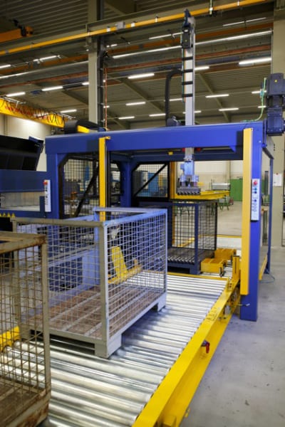
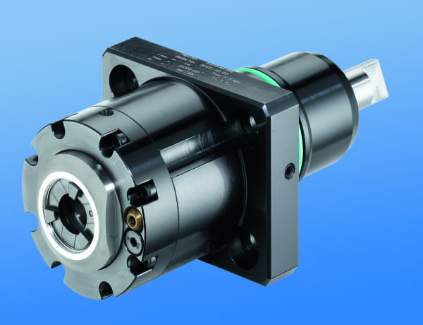
The ACS Sawing Machine is the new industry standard for cold saws. It utilizes a proprietary sawing algorithm with servo motor controlled feed to continuously adjust critical sawing parameters during each cut. The results are the fastest sawing times, best surface finish and longest blade life available on the market.
Precision parts are made in one continuous process with no operator intervention. Bundles of mill length stock, up to 16.5 meters (54’) long, are placed in an automatic loader, individually separated and fed to the sawing process. Cut parts are then transferred to the CFMcurve machine for precise finishing. Utilizing advanced CNC controls, linear ball screws and servo motors, all mechanical motion is seamlessly integrated into the machine design for full process control.
The technology incorporated on this manufacturing center delivers production rates and quality unmatched by the competition. For example, a tubular component of 70mm diameter, wall thickness of 5mm, material type ST52-3 BK, with a length of 150mm, machined with a 30 degree chamfer on the ID & OD with a faced end has a saw time of .96 seconds, a machined time of 1.86 seconds and the machine can produce 1,820 parts per hour, inspected for length and automatically packaged. Cut length tolerance of +/- 0.15mm at 1.67 CPK and a machined length tolerance of +/- 0.05mm at 1.67 CPK are maintained with consistency.
The operator interface saves part files for instant recall when changing parts. Servo motors move all cutting and machining tools to their exact positions and implement saved parameters. No tooling change is required in the ACS Saw within a diameter range of 10mm; there is a 5mm diameter range in the CFMcurve. Tooling change for the complete system takes less than 20 minutes, when necessary.
All critical sawing and machining parameters are monitored and controlled. Clamping forces and position, saw blade torque and vibration, plus machining insert torque are continuously displayed and monitored. Operating limits are set and machine functions stop when they are not met. Saw blade and tooling insert wear is predictable and consistent. Key data for each part produced are stored in memory for statistical evaluation. All guesswork is removed for the operator.
Rattunde sets a new industry standard for manufacturing with this machine, replacing slow and unreliable processes with a complete manufacturing center. Bar feeding lathe machines rely on a slow cutoff process, restrict the length of incoming stock and are not always capable of finishing both part ends simultaneously. Cutting in a conventional saw, dropping parts in a bin and eventually loading them to a conventional machining center is time consuming, labor intensive and creates excess inventory with a loss of process control.

The ACS + CFMcurve is available in three models with diameter ranges from 10mm to 102mm, 10mm to 136mm and 10mm to 169mm, with finished part lengths from 10mm to 3500 mm. All material types can be processed.
You can watch the machine in action at:
http://www.rattunde-corp.com/tube-sawing-video.htm
For further information, please contact:
Rattunde Corporation
4980 Kendrick St. SE
Grand Rapids, MI 49512
616-940-3340
Alec Banish
a.banish@rattunde-corp.com
www.rattunde-corp.com
Aquatic Development Group uses specially modified Amlok® product from Advanced Machine & Engineering to protect movable pool floor stability at Ithaca College

AFW™ pool raising and lowering system, designed by Aquatic Development Group, operates on a series of hydraulic rams connected by a rebar structure, to evenly and smoothly raise and lower the pool floor. Especially useful when floor is occupied by aquatic therapy patients or water aerobic participants.
Aquatic Development Group (ADG) of Cohoes, New York is a professional design, manufacturing and construction firm serving the waterpark, resort, hotel aquarium, aquatic therapy and commercial/institutional swimming pool markets. The company’s recreational aquatic creations range from Disney to the Wisconsin Dells, plus a diverse group of institutional and physical therapy applications are included in the company’s successes. Among ADG’s many unique designs is the AFW™ movable pool floor system that allows depth adjustment from deck level down to deeper water for various uses, including physically-challenged patient aquatic therapy. The system is also used routinely in pools adapted for competitive swimming, diving, water polo and other activities, where the depth adjustment is beneficial and allows more multi-purpose use of a facility.
At the touch of a button on the master control module, the pool floor is raised and lowered by a system of synchronized multiple hydraulic cylinders that work to maintain consistent floor level throughout the process. ADG determined it was necessary to include a mechanical locking system that would secure the cylinder rods in position, at all points of travel, especially when the floor was occupied by physical therapy patients, water aerobics participants etc. The floor also featured a passive mechanical pulley system to maintain the floor position in the event of a catastrophic hydraulic failure.
On a recent project using this system at Ithaca College (Ithaca, New York), as ADG Engineering Manager Rob Schiavi details, “We had a four-cylinder ram system with a rebar structure that was designed so that any two diagonally opposed cylinders could malfunction without compromising the stability or safety of the floor and its occupants.” He also notes that the company had developed a special 304L stainless steel and non-skid, chemically-impervious PVC floor grating that was considerably lighter weight but somewhat less stable than conventional concrete pool flooring.
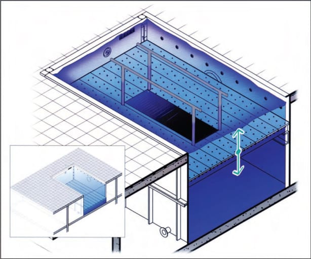
The hydraulic circuits operate on a shuttle valve system with passive engage ram failure. Eliminating the mechanical pulley system on the design results in a smoother transitioning of the pool floor level, particularly important when people are present, Schiavi notes.
In designing the hydraulic ram system and in search of an appropriate cylinder locking protection system, ADG turned to its local subcontractor, who recommended the Amlok® system of hydraulic cylinder rod locks from Advanced Machine & Engineering (Rockford, Illinois), a longtime supplier of hydraulic and pneumatic rod locks to industrial and commercial applications worldwide. AME Business Development Manager Ken Davis explains, “We saw this project as an ideal application for our hydraulic rod locks, with one particular challenge, namely, the ingestion of chlorinated pool water.” To overcome this challenge, a modification was made to the seal design and materials on the four stainless steel rod locks to be installed on the ram system built by ADG’s subcontractor (click here for ram system specs). Each lock has the capacity to provide a locking force to 50,000 lbs. at 1500 psi release pressure (click here for locking force specs).
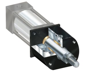
RCH Series Amlok® hydraulic rod locks hold cylinders in place and automatically seize cylinders in position, in the event of a catastrophic power loss.
During normal operation, the hydraulic rod locks used on this application (RCH Series) allow free movement of the cylinder through the lock housing, as the supplied hydraulic pressure maintains an open position on the lock. When the desired pool floor level is achieved, the hydraulic pressure is removed and the cylinder is mechanically locked into position. However, in the event of a catastrophic power loss or other hydraulic system failure, when the pressure is removed, the lock immediately clamps to retain the cylinder securely in its present position until power is restored and the lock release is again activated.
AME worked closely with its local distributor, Airline Hydraulics Corp. (Bensalem, Pennsylvania) to supply this system to ADG.
For more information on this story, please contact:
Rob Schiavi, Engineering Manager
Aquatic Development Group
13 Green Mountain Drive
Cohoes, NY 12047
Phone: 518-783-0038
Web: www.aquaticgroup.com
Or
Ken Davis, Business Development Manager
ADVANCED MACHINE & ENGINEERING CO.
2500 Latham St.
Rockford, IL 61103
Phone: 815-316-5277
Fax: 815-962-6483W
E-mail: info@ame.com
Web: www.ame.com
Connect with AME online:
Increasing demands made on precision and the push for the decrease of price of modern components is pushing traditional manufacturing processes to their limits. From September 10th-15th, 2012 at IMTS in Chicago, IL, EMAG will present three production technologies that complement or replace traditional processes such as turning, milling and grinding.
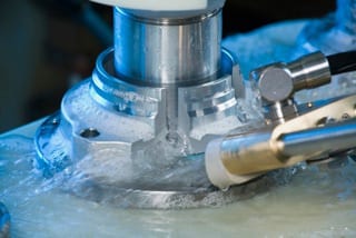
The ECM process is used to deburr components only at the points where material needs to be removed, and without it having any mechanical or thermal impact on the workpiece.
PECM for nickel- and titanium-based alloys
With its PECM technology (Precision Electro-Chemical Machining) EMAG presents a production process that opens up completely new fields of application. PECM is a process for the machining of high-alloyed materials, such as nickel- and titanium-based alloys. The disadvantages of traditional metal cutting – tool wear, mechanical stresses, micro-fissuring caused by heat, oxidization layering and the need for subsequent deburring operations – are eliminated, because this process is a non-contact one without heat input. All electro-chemical machining processes are characterized by stress-free material removal, smooth transition points and surfaces without ridge formations.
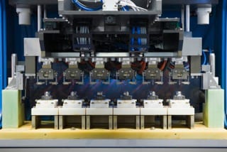
Six in one – the EMAG ECM deburring process can be adjusted to suit individual production requirements.
The advantages that the PECM process provides for different branches of industry are best shown with the example of a turbocharger for the automotive industry. The electro-chemical process is one that can be used to effectively in the machining of many high-alloy components, especially those in the high-temperature sector of the turbocharger – it also offers a much shorter and very efficient process chain. The typical clean-up operations necessary when traditional machining processes are used – such as deburring after milling – are no longer necessary. PECM machining operations are burr-free. And there is hardly any tool wear. The result: downtimes are minimal, when compared to milling (which requires regular tool changes). The process as a whole is sturdier and less prone to errors. And another important factor that our example of the turbocharger shows: the superb surface finish of the PECM process, where Rz-values of 0.3 micron can be achieved.
Will camshafts ever again be made of a single piece?
Another highlight is EMAG‘s heat-shrink assembly technology, a process that scores particularly well in camshaft production. The high degree of precision achieved with the joining process drastically reduces the number of cam profile grinding operations or – with the use of precision cams – avoids them altogether. Another benefit of the process is the ability to combine different materials in the construction of the shaft, such as forged cams (e.g. in 100Cr6) and sintered cams, which do not require regrinding. Accessory components, such as plugs and end pieces, can – like the shaft itself – also be made of better materials. This allows for the camshaft to be adapted to the requirements of the engine and to be optimized in load bearing capacity and manufacturing costs.
Operating costs reduced by 50 %
Production laser welding is already a highly productive process in the manufacturing of gearwheels. The use of diode-pumped solid-state lasers – such as disc or fiber lasers –reduces operating costs by up to 50%. EMAG has been involved with the use of solid-state lasers in the welding of powertrain components from an early stage and is considered a pioneer in the technology. EMAG again has fulfilled a promise to their users offering them the lowest possible cost-per-piece, by coming up with an innovative technology that brings true cost benefits.
For many applications, solid-state lasers allow welding without shielding gas. This not only reduces operating costs, it also avoids having to follow the annoying logistics imposed by the use of shielding and laser operating gasses. In many cases, the welding process can also be sped up considerably. This increases productivity and – through a reduction in energy input per unit length – reduces welding distortion, resulting in better component quality.
For more information:
EMAG LLC
38800 Grand River Avenue
Farmington Hills, MI 48335
Tel: (248) 875-0313
Fax: (248) 477-7784
E-mail: info@usa.emag.com
Web: www.emag.com
Attention: Peter Loetzner
Continue readingHigh component quality with low production costs is required in many applications involving machining chucked parts. At IMTS, September 10 – 15, 2012 in Chicago, EMAG will be showing these solutions which combine these requirements. One of the highlights at the show will be the introduction of the brand new VL 2 P, a vertical pick-up turning machine which operates using pendulum technology.
Whether you want to manufacture small chuck parts or larger components, the machining processes must ensure accurate component geometry while also guaranteeing low component costs. These requirements and more are met with the VL 2 P and VL 5i vertical turning machines as well as the VSC 400 DDS turning and grinding center from EMAG. The advance in productivity is provided by the EMAG design of these machines with the integrated pick-up automation and a machine body made of polymer concrete as well as the vertical design which ensures perfect chip flow conditions.
VL 2 P: Swinging to success
Workpieces up to 100 mm in diameter can be machined in full on the innovative VL 2 P, a two-spindle turning machine. The machine has two spindles because while one workpiece is being machined, the second spindle automatically loads itself using the pick-up method. This means that the next raw part is immediately ready for machining, resulting in extremely short chip-to-chip times. The focus during the design of this machine was efficiency and eliminating idle times. The VL 2 P also has an incredibly small footprint due to its compact design, which helps decrease the chip-to-chip times. See it in action at IMTS 2012 HERE.
VL 5i: Short idle times, perfect automation
The VL 5i turning machine is a universal solution for production companies. It can completely machine workpieces of up to 250 mm in diameter in a single clamping operation. In addition to the powerful pick-up working spindle with a rating of 28 kW and a torque of 300 Nm, the machine also has an automation system with a revolving belt which contains drag frames. The machine could be described as being self-automated, which means that new raw parts can be positioned and finished parts removed at any time. Another strength of the VL 5i is its short idle times because the distance between the loading and the machining positions is just 550 mm.
VSC 400 DDS: Grinding and turning combined
The VSC 400 DDS vertical grinding and turning center combines a range of processes and guarantees extremely cost-effective processes in the production of complex chuck parts with a diameter of up to 400 mm. Within a single clamping operation, the center can complete scroll-free turning and hard turning as well as subsequent grinding processes. Grinding is only used where quality and process reliability demands it. The center can also be fitted with drilling tools or hardening modules to suit the required machining task. Even measuring tasks can be integrated.
For more information:
EMAG LLC
38800 Grand River Avenue
Farmington Hills, MI 48335
Tel: (248) 875-0313
Fax: (248) 477-7784
E-mail: info@usa.emag.com
Web: www.emag.com
Attention: Peter Loetzner