
Contact us today:
Author Archives: Bernard and Company
JAC Products Uses Flex Shaft Drills for Increased Roof Rail Production
By Bernard and Company
No Comments
Franklin, Georgia Tier One automotive supplier realizes up to 70% greater output from its internally designed production equipment, utilizing Suhner advanced drilling technology
See the video here!
JAC Products (Franklin, Georgia) puts 30-40 million holes into approximately 6 million pieces of extruded and formed aluminum each year. The products made at this facility are used as roof rack rails on nearly every major automobile, mini-van and truck brand. This fact translates into a majority share of the North American vehicle market for JAC.
As Mike Traylor, the JAC tool room & die shop manager notes, “We build and maintain nearly all our own machinery here in our factory. That means the whole team must keep striving to find greater efficiencies and new ideas.” As a vertically integrated manufacturer, JAC operates hundreds of drilling stations in its Franklin factory, located on the banks of the Chattahoochee River in southeastern Georgia. In the company’s extrusion department, millions of pounds of aluminum are extruded annually from 6061, 6063 and 6463 alloys. The extruded shapes then move to the fabrication department, where they are formed and drilled on highly automated equipment to produce the finished products. Following a decorative and wear-resistant finishing operation, JAC performs the final assembly of the products and ships directly to the customer’s assembly line.
A tour of this facility strikes the visitor in several ways. First, there is a steady flow of material between departments and very little wasted motion, as every station at JAC is a dedicated operation producing an average of 100,000-200,000 left- and right-side rail sets per year for each specific automobile model.

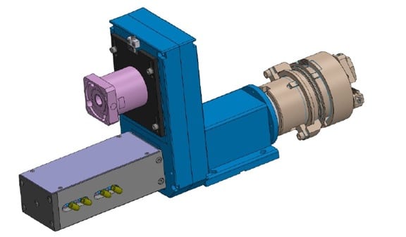
Suhner motor/drill combination allows precise repeat holes
Another point of note is the openness of the machinery. That condition results, according to Traylor, from one very important supplier to JAC, one that has been a partner to this Tier One for nearly 20 years. Suhner Automation Division, based in nearby Rome, Georgia, supplies an assortment of flex shaft and direct motor-driven drilling units to JAC, where Traylor’s team of mechanical specialists incorporates them into the company’s internally-designed production equipment. Owing to the flex shaft design on many drills, the drive motors are removed from the cutting area, making accessibility much better not only for operators and maintenance personnel. This configuration also improves access to other equipment such as laser trackers and position sensors. “The bottom line, as they say, is that we get upwards of 60-70% more output from our equipment since we began using the Suhner solutions for our drilling,” notes Traylor. The previous drills used here were also prone to breakdowns and service problems, which caused unacceptable delays in production, especially as the industry transitioned to the just-in-time philosophy. As Mike comments, “If JAC was going to keep up with JIT, we needed a more reliable supplier and better ergonomics on our equipment to improve the output.” He contacted an associate from a previous company relationship, Charles Stitcher, the regional marketing manager from Suhner, who presented his company’s solutions in flex shaft and related drilling devices. “It was a light bulb moment for our company,” says Traylor, “because we knew we’d found an answer to a lot of our challenges.”
By taking the motors out of the drilling area, the JAC operators could have much freer access to the work product, while the maintenance personnel could access a single manifold in many cases to do repairs, routine maintenance or replace components. Most of the machines designed here are dedicated pieces of equipment, used to produce a single rail set for a particular model, then retrofitted or rebuilt for the next generation, next model year design, or a completely different vehicle by Traylor’s team. The flex shaft design gave the machine building and maintenance group at JAC a significant advantage and it has continued to benefit the company in many ways, according to Traylor. “We can now use a more compact work area concept, which saves operator steps. Seems like a little thing, but when you do the math and the motion study, it represents a huge annual savings for our company, without sacrificing any safety considerations for our workforce.”
As one might guess, JAC understands the fabrication process for putting holes into aluminum, whether for roof mounting, rivet placement, or trim assembly. Often, the angle of the drill must be oriented to the surface of the workpiece, rather than in a typical x-y planar arrangement. Here again, the flex shaft design of the Suhner drills pays big dividends for the machine designers at JAC, as it allows them to position the drilling mechanisms in various configurations and tighter proximities. This allows the required accuracies, secondary counterbore operations or other processing steps to occur. After working on nearly 500 machine builds at JAC, Mike Traylor says he’s been very impressed with the flex shaft drill and its adaptability on a wide variety of applications.
“On one rail set for a Ford vehicle and another for a Toyota vehicle, the old way would have involved one operator performing all the drilling, one step at a time. Today, we have up to 11 drills and a cutoff operation, all performed at once. The savings in setup time alone are off the chart.” He cites another job where the output was previously 1200 sets per day and is currently 1200 per hour.
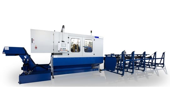
Not all of the drilling here is done with flex shaft models, however. On several dedicated machining operations, various Suhner motor-mounted drills are utilized, including a specially designed system for sawing.
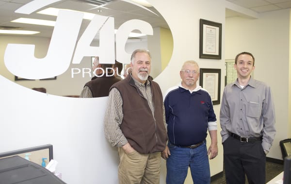
Jeff Cavalier, Mike Traylor and Alberto Blanco of JAC Products in Franklin, GA
Senior Launch Manager at JAC, Alberto Blanco, comments, “We need to hold +/- 0.1-0.2mm tolerances on the drilling and +/- 0.5mm on our cutoff lengths for our customers, so the Suhner equipment capability has been very favorable in helping us deliver our value proposition to customers.” Traylor adds that the drills are used virtually non-stop, so wear is inevitable, further noting the availability of Suhner rebuild kits, including o-rings and seals, makes maintenance much easier for his team.
Finally, Jeff Cavalier, the JAC engineering & facilities manager notes, “With the support we get from Suhner, we know Mike and his team can make it happen, every day, creating and maintaining the machines that get the job done for our customers. That’s a nice feeling.”

SUHNER INDUSTRIAL PRODUCTS, CORP.
Hwy 411 S./Suhner Drive
P.O. Box 1234
Rome, GA 30162
Phone: 706-235-8046
Fax: 706-235-8045
Attention: Lee Coleman, Automation Division
www.suhner.com
automation.usa@suhner.com
Text and pictures files can be found and down loaded at:
www.suhner-press.com
New Range of Indicators for Force Measurement: Type 1020-FMD
By Bernard and Company
No Comments

Penko Type 1020-FMD Force Measurement Indicators
New force measuring instruments need to have more functions and features, be smaller and offer more value for the money. PENKO responds to this challenge with its new product range, Type 1020-FMD. These instruments are suitable for automatic as well non- automatic applications. They are an ideal interface between load cells with an integrated controller to the system for data processing.
The unique PENKO way of measuring with high-speed of 1600 conversions/sec and high internal resolution, 24 bit, guarantees a fast and accurate data transfer and/or cut-off. These characteristics allow application of the instruments for static and dynamic force measurement as well as destructive material tests. These applications are supported with zero adjustment, track recording, hold/peak, hold/valley, hold and overload protection.
As a standard, all Type 1020-FMD models are provided with USB to facilitate set-up and back-up functions. Additional models include RS232, RS485/422, Ethernet, CANBUS and Profibus. The range is completed with an analog output, 0/4 – 20/24 mA. Easy and fast calibration is done digitally. The force is displayed by means of a bright 2.8” TFT screen with 13 mm high figures, plus a color bar.
Choose from two enclosures, a compact panel model and stainless steel housing.
• The panel meter has a front of 150 x 76 mm and a depth of only 82 mm;
• The stainless steel enclosure size including the swivel bar is 180 mm x 145 mm x 153 mm (W x H x D).
For easy selection, a free brochure is available: 1020 Series Brochure.
Contact:
Susanne Krause, Marketing Director
Penko Engineering B.V.
Schutterweg 35
Ede, The Netherlands
Phone: +31 (0)318 525 630
www.penko.com
skrause@penko.com
In the United States:
Karl Cornelius, National Sales Manager
Powerforce LLC
229 Dunavant Road
Rockford, TN 37853
Phone: 865-318-5532
www.powerforceusa.com
karl@powerforceusa.com
Suhner and WAGNER Partner to Optimize Threading Operations
By Bernard and Company
No Comments
Operations for the prep on tubings and pipes generally require multiple manufacturing steps such as cutting, chamfering, face-off, turning and tapping including thread milling or thread forming.
Higher part quantities usually combined with the need for different manufacturing steps demand efficient and time saving production methods to help reduce time and cost. Special purpose machines such as rotary & linear transfer machines, offer the best solutions to help obtain shorter overall part cycle times.
The machining of tubings begins from bar stock length
The transfer machine performs OD and ID turning incl. chamfering oerations followed by thread rolling.
An extensive background of experience with operations on transfer machines allows SUHNER to optimize a manufacturing process with standard or custom solutions for each machining application. One specific application is for large & long OD threads. These operations are extremely difficult and challenging for manufacturers, when trying to obtain shorter cycle times, simply because an OD threading operation by itself will dictate the overall machine cycle time.
SUHNER, in cooperation with WAGNER, a German manufacturer for OD thread rolling heads, has developed a special process, which allows threading operations in very short cycle times. A pneumatic cylinder-activated system is used to open and close the thread rolling head, which is equipped with multiple thread cutting or forming inserts.
Special unit BEX35 ISO40 equipped with WAGNER Z27-2 thread rolling head allows optimized OD thread rolling operations and shortened machine cyle times
The work piece is fed from bar stock material. After a cut to length operation, it is machined by (3) Suhner BEX15 machining units with special Weldon tool holders. Operations include OD & ID and face turning. All units are equipped with a 1.5kW motor and high precision angular contact spindle bearings.
The most interesting station on this machine is the one for an OD threading operation, which is accomplished with a BEX35-ISO40 machining unit equipped with a WAGNER Z27-2 thread rolling head. In this operation, the thread rolling head is rotating and the work piece is stationary. The feed motion for this station is done with a CNC slide unit. In order to synchronize the thread pitch, both the BEX35 spindle and CNC slide are servo motor driven.
As soon as the threading operation is finished, the WAGNER thread rolling head with integrated inserts opens quickly to allow a fast return to the home position.
Opening and closing action of the head is accomplished by an internal BEX35 drawbar, controlled by a 3-position pneumatic cylinder.
This pneumatic cylinder is designed to make an additional stroke of 10mm. This allows for head and insert adjustments or replacements, depending on thread size.
Depending on length, a typical OD thread rolling cycle time ranges between 6 -10 seconds. Illustrated work pieces are steel tubings as used in the HVAC product industry. There are 7 part variations, each with a different thread size, pitch and length requirement. Thanks to the application of CNC servo driven spindle and slide components, customers can achieve very short changeover time, as well.

SUHNER INDUSTRIAL PRODUCTS, CORP.
Hwy 411 S./Suhner Drive
P.O. Box 1234
Rome, GA 30162
Phone: 706-235-8046
Fax: 706-235-8045
Attention: Lee Coleman, Automation Division
www.suhner.com
automation.usa@suhner.com
Text and pictures files can be found and down loaded at:
www.suhner-press.com
An Inside Look at CT Scanning
By Bernard and Company
No Comments
First application of CT scanning for metrology in America involves aluminum casting
Josh Schradin, one of the 3D Scanning specialists at Exact Metrology’s Cincinnati facility, recently completed a CT Scanning project involving aluminum castings measuring approximately 12” x 6” x 6” and weighing 10 to 15 pounds.
 The company’s new Metrology Grade GE v|tome|x 300 CT Scanner, with Nanofocus Tube (180kV/15 W) and Microfocus Tube (300kV/500W), is equipped to “look inside” aluminum to a wall thickness or total amount of material of six to seven inches, or steel to a wall thickness or total amount of material of one inch.
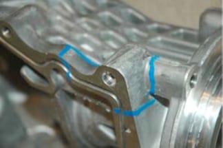
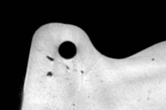
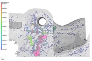
For this particular job, which represents the first use of CT scanning for metrology in America, the client was interested in wall thickness inspection as well as porosity and void analysis. The blue paint visible in some of the images was applied by the customer to indicate stress areas where leaking or breaking was suspected. Josh Schradin performed three stacked scans, each taking only about 30 minutes, to capture the entire casting. The result of the scans revealed the voids (legitimate holes) and highlighted the most serious problem areas in red-to-pink shadings.
In addition to offering the only method to get 3D views inside a part, another primary benefit of the Exact Metrology CT scanning is the true dimensional data provided in a non-destructive test manner, i.e. without cutting up or otherwise destroying the test object.
The workpiece (casting) was rotated 360 degrees in the x-ray beam’s path, with multiple readings from various angles being taken. Once the CT grey scale images were converted into voxel-based 3D point clouds, Schradin was able to generate a CAD-to-Part comparison for the customer.
If interested parties have a need for Internal Defect Analysis/3D Quantitative Porosity Analysis, Materials Structure Analysis or Assembly Control, CT Scanning (Industrial X-ray), Exact Metrology invites inquiries for immediate assistance.
Exact Metrology is an ISO 9001:2008 Certified Company.
To see videos on this new scanner’s capabilities, please visit:
VG GE casting analysis with CT hi-res at Exact Metrology
v | tome | x m CT scanner at Exact Metrology
For more information on this new system or to arrange a demonstration, please contact:
EXACT METROLOGY, INC.
11575 Goldcoast Drive
Cincinnati, Ohio 45249
Phone: 513-831-6620
Toll Free: 866-722-2600
www.exactmetrology.com
stevey@exactmetrology.com
Steve Young, President
Connect with Exact Metrology online: ![]()
![]()
![]()
![]()
![]()
—
Exact Metrology, with facilities in Cincinnati and Milwaukee and affiliated offices throughout the Midwest, is a comprehensive metrology services provider, offering customers 3D scanning, reverse engineering, quality inspection, product development and 2D drawings. The company also provides turnkey metrology solutions, including equipment sales and lease/rental arrangements.
Continue reading500°F Universal Oven for Heating Heavy Metal Dies
By Bernard and Company
No Comments
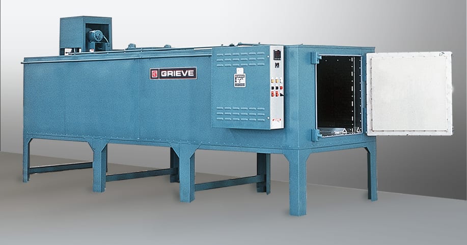
No. 980 for post curing fabric-coated silicone rubber gaskets | #GrieveCorp
No. 980 is a 500ºF (260ºC), electrically-heated universal style oven from Grieve, currently used for post curing fabric-coated silicone rubber gaskets at the customer’s facility. Workspace dimensions of this oven measure 30” W x 144” D x 30” H. 24 kW are installed in Nichrome wire elements to heat the oven chamber, while a 4200 CFM, 3-HP recirculating blower provides front-to-rear universal airflow to the workload.
This Grieve universal oven features 4” thick insulated walls, aluminized steel exterior, Type 304, 2B finish stainless steel interior, plus an integral oven leg stand and one pair of truck wheel guide tracks installed on the top of the floor to accept the customer’s wheeled fixture.
No. 980 includes all safety equipment required for flammable solvent processing, including explosion-venting door hardware and powered forced exhauster.
Controls on this oven include a digital indicating temperature controller.
For more information, please contact:
THE GRIEVE CORPORATION
500 Hart Road
Round Lake, IL 60073-2898
Phone: (847) 546-8225
Fax: (847) 546-9210
Web: www.grievecorp.com
Email: sales@grievecorp.com
Attention: Frank Calabrese, VP
“The Bullet™” Extrusion Head from Guill Tool
By Bernard and Company
No Comments
New extrusion head from market leader features NO hardware, for easy cleaning, plus quick-change tooling, as tips removes from the back, die from the front
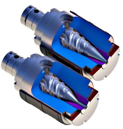
The Bullet, showing the absence of hardware, i.e. nuts and bolts, so disassembly, cleaning and restart are made easier
Guill Tool introduces The Bullet™, a new extrusion head with fixed center design, multi-port spiral flow design and gum space adjustment, plus the added feature of no fastening hardware, so cleaning and restart are easier and faster than any conventional head on the market currently, according to company sources.
The Bullet allows quick tooling changes, as the tips remove from the back and the die removes from the front of the unit. The absence of fastening hardware eliminates leaking, as does the taper body and deflector design pioneered by Guill.
High- and low-volume applications are suitable for this head and are accommodated with the simple, easy changing of just one component. A family of crosshead designs is available and users can specify the “caliber”, that is, the max. die ID.
A vacuum chamber and kit for assembly and disassembly are included with the unit. Optional keyed tooling capability offers machine designers and end users quick orientation, so the overall unit design enables faster disassembly, proper cleaning and restart, allowing the line to become more profitable.
For further information, please contact:
GUILL TOOL & ENGINEERING CO., INC.
10 Pike Street
West Warwick, RI 02893
Phone: 401-828-7600
Web: www.guill.com
Email: sales@guill.com
Attention: Bill Conley
Connect with Guill Tool online: ![]()
![]()
![]()
WESTEC 15 – Suhner BEA 16 Universal Machining Unit
By Bernard and Company
No Comments
See it at WESTEC 2015 – Booth 551!
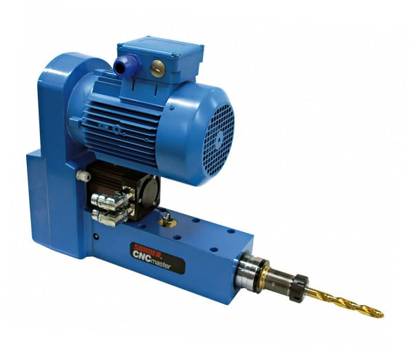
Following its successful launch, SUHNER is presenting the BEA 16 spindle machining unit with an all new drive and control concept.
The objective of this new development was the integration of the latest servo drive and control technology from Bosch Rexroth. Software developed additionally allows the user to program six different basic cycles without prior knowledge of CNC.
By visualizing these six cycles – drilling – combined drilling (drilling and thread cutting with the one tool) – thread cutting – drilling with chip removal – drilling with jump function – undercutting, the unit has become extremely easy to program.
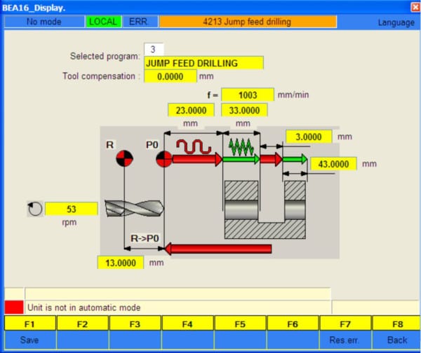
Example of a drilling cycle with jump function | Suhner Automation BEA16
Plus, should the required machining cycle not be found among the standard selections or prove more complex, the unit can be switched to sentence programming.
The BEA 16 machining unit itself is a precision device from the SUHNER spindle machining unit series that has been designed for gruelling continuous use in multiple shift operations. The BEA 16 has a drilling capacity of 16 mm Æ in 450 N/mm2 steel. The max feed path is 140 mm, and the max speed is 500 rpm.
Today, rising production piece numbers and greater workpiece complexity with all-round machining are leading to a renaissance of the so-called special machine. However, today’s special machines are being used no longer as purely single-purpose solutions, but rather for whole part families.
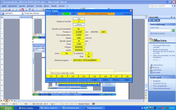
Example of a sentence programming | Suhner Automation BEA16
These require different machining cycles, feed speeds, feed paths and rotating speeds, and, of course, must allow fast retooling. And it is these requirements exactly that the BEA 16 will meet to the full.
SUHNER INDUSTRIAL PRODUCTS, CORP.
Hwy 411 S./Suhner Drive
P.O. Box 1234
Rome, GA 30162
Phone: 706-235-8046
Fax: 706-235-8045
Attention: Lee Coleman, Automation Division
www.suhner.com
automation.usa@suhner.com
Text and pictures files can be found and down loaded at:
www.suhner-press.com
Exact Metrology Holds Tech Event At Horseshoe Casino
By Bernard and Company
No Comments
Product demonstrations and technical presentations from principals impress large crowd
On June 25, 2015, Exact Metrology held a tech event at the Horseshoe Casino in Hammond, Indiana for local companies, to demonstrate its new 3D scanning equipment. Cleverly titled “Don’t Gamble with Your 3D Scanning,” the event was attended by local area industries, including steel, oil & gas and power gen “players”.

Hosted by Dean Solberg, Exact Metrology co-president, the day included presentations by Leica GeoSystems and Hexagon Metrology, business partners of Exact, plus product demonstrations featuring the newest technology in 3D scanners. Several scanners were demonstrated and available for hands-on use by the attendees, including the Romer Absolute Arm, the Leica Absolute Tracker and the Leica T-Scan.
Attendees were impressed by the ease of use, speed and accuracy of the demonstrated models, with scanning capabilities of over one million points per second. Bruce Bowditch of Leica described them as “a survey total station on steroids.”

Attendees could be heard discussing their excitement and one steel industry engineer commented, “That specific type of scanning can be applied to a lot of what we do. Pumps need to be scanned to assure proper fit. The Romer Absolute Arm is definitely quicker and more accurate. Our current process is so cumbersome; there’s just no comparison.” After trying out the Leica Absolute Tracker, one attendee in the oil industry stated, “Speed and accuracy is what we’re after. We have a model that does about half of what this can do. A lot less field time…hoping to get one. We’re excited.”
Exact Metrology offers a complete line of portable scanning and measurement technologies as well as contract measurement for 3D laser scanning services, reverse engineering services, non-contact inspection, metrology services, 3D digitizing and training.
See all the photos from the event on Facebook, here.
For more information on any of the systems discussed or to arrange a demonstration, please contact:
EXACT METROLOGY, INC.
Dean Solberg
20515 Industry Avenue
Brookfield, WI 53045
Phone: 262-533-0800
Local: 866-722-2600
www.exactmetrology.com
deans@exactmetrology.com
—
Exact Metrology, with facilities in Cincinnati and Milwaukee and affiliated offices throughout the Midwest, is a comprehensive metrology services provider, offering customers 3D scanning, reverse engineering, quality inspection, product development and 2D drawings. The company also provides turnkey metrology solutions, including equipment sales and lease/rental arrangements.
Synergy Systems Retrofits Blast Furnace & Stove Control System at Major Midwest Steel Producer
By Bernard and Company
No Comments
Sequenced changeover of all process control parameters yields successful implementation of system upgrade with minimal downtime
Lisle, Illinois – Synergy Systems, Inc., a consulting engineering firm and Recognized System Integrator for Rockwell Automation, today announced the completion of a successful upgrade on the main blast furnace and stove control system at a major Midwest steel producer. Unique to this 18-month project was the absence of production downtime experienced by the client, during the transition from legacy control system elements to a Rockwell Automation ControlLogix and Wonderware-based HMI platform. Synergy Systems termed its protocol on this project the System Transition Execution Plan (STEP). During the implementation of STEP, the client experienced no interruption in overall blast furnace or stove control system operations, as it transitioned from an older DCS (distributed control system) to the new system, which was entirely designed and installed by Synergy Systems engineers, working onsite at the steel mill with client personnel.
At the heart of the concept, according to Synergy Systems VP Marc L. Hunter, “We developed our strategy around a core principle that targeted zero downtime during the changeover. Essentially, we created a building block operation, in which each control input/output on the old system was upgraded with parallel monitoring of performance values and system readouts. Only when each new component was functioning properly and the signals were inline with the existing monitored values did we execute the changeover of the control strategies, which was then integrated loop-by-loop into the new process LAN.” Utilizing this strategy, Synergy Systems enabled the client to maintain full production at the mill, throughout the entire project. Client engineering confirmed their complete satisfaction with the performance on this major project.
The STEP upgrades included all the following procedures: replacement of legacy PLC hardware with AB ControlLogix, replacement of DCS/PLC interface, movement of I/O from DCS to ControlLogix, deployment of Wonderware HMI, movement of control from DCS to ControlLogix, Wonderware historian integration and finally Level 2 interface via Wonderware HMI. Essentially, the control scheme for each system element was installed in parallel to the legacy control, then connected to the new ControlLogix processor and monitored on a channel of the client’s overall process control LAN for comparison to the older output.
Using this STEP approach, minimal process impact occurred and there was a significant savings realized for the client, both in operational expense and total project cost. As Hunter explains, “This project, because it happened in steps, so to speak, could be costed as a maintenance, not a capital, expense. The major capital expenditure diminished, owing to our strategy of loop-by-loop cutover and a gradual evolution of the graphical user interface, plus a progressive integration with the plant historian software. Collateral benefits to the client included a gradual weaning away from the legacy system, which allowed our team to thoroughly familiarize our client’s operational and maintenance personnel with the new hardware and software, as the changeover progressed.”
The determination to upgrade this system had resulted from numerous factors, according to the client. The I/O had become obsolete and the legacy system was UNIX-based, so many of the client’s current engineering staff onsite were not familiar with it. However, because a need existed to retain overall control strategies and functional client knowledge of system operations, Synergy Systems devised this STEP protocol to make the transition more gradual and self-teaching.
According to the client’s plant production & technologies manager on the project, “The blast furnace and stove control systems needed to be upgraded from a legacy DCS (Distributed Control System) to a Rockwell Automation PLC (Programmable Logic Controller) platform, with Schneider Electric Software Wonderware human machine interface and historian, along with statistical reporting mechanisms. Synergy Systems was challenged with cost-effective project deliverables requiring a proven transition plan, zero production outages, minimal risk implementation with no impact to production or product quality, improved technology with future expansion capabilities, improved process controls, enhanced operator interface, significant improvements to system reliability and stringent budgetary guidelines. This project required verification and movement of nearly 2000 I/O points, installation of new workstations, network communication upgrades, development of over 60 HMI screens with built-in diagnostics and alarms, extensive PLC programming, system functional documentation development and drawing approval, historian upgrades and onsite training. Finally, total project implementation and completion were required within a two-year period.”
He continued, “Synergy delivered beyond our expectations on every challenge presented. The innovative approach, level of engineering delivered and tools selected ensured a successful transition without impact to our production or product quality. Synergy’s professional manner plus their willingness to listen and offer solutions always made it easy for our Operations and Automation team personnel to work with them. The upgraded control systems have been in operation for nearly a year now, with high levels of reliability and efficient operations realized. Synergy proved to be an extremely cost-effective yet resourceful company, with a focus on the future of our mill control requirements. Our plant now has the technology to further enhance the automation strategies and drive flexibility and productivity that were not available with the legacy automation platform.”
For more information on this application, please contact:
Synergy Systems, Inc.
1982 Ohio Street
Lisle, IL 60532 USA
Phone: 630.724.1960
www.synsysinc.com
info@synsysinc.com
Attention:
Marc L. Hunter, VP
hunter@synsysinc.com
Whitepaper: Control Strategies for Web Handling
By Bernard and Company
No Comments
PLC, drive and motion-based functionality and architecture
Abstract
There are several architectural strategies that can be considered for web handling drive system controls. Current industrial control platforms permit the web handling controls to be implemented in either a Programmable Logic Controller (PLC) (typically the same as the machine control), directly in the drive system, or through a motion controller.
PLC-based web control has long been a traditional choice for machine builders for a number of reasons. The PLC provides a single platform for both automation and drive control with a centralized control structure. PLC-based systems offer a suitable level of usability, however, they can be limited in high-end performance capability and in their options for process-level programming.
Drive-based control typically offers distributed control architecture, peer-to-peer networks and an increased level of performance due to faster processing times. Graphical engineering tools are common for drive-based systems and are a preferred programming environment due to their ability to visualize and document the web control processes.
Motion controllers offer the highest level of performance and functional flexibility. Their inherent capability of providing position data can help increase web handling performance on several fronts. Motion controllers also permit the line integration of axis motion functionality such as positioning, electronic gearing and cam functionality in the common web controller. They are not limited by memory constraints and typically utilize the full range of programming languages.
This paper will review the merits of these three control architecture options in detail under the criteria of usability, functionality and performance, and also touch on the related topics of drive safety and remote diagnostics.
Overview / criteria
Usability
Usability defines the control system’s ease of use in the areas of engineering, commissioning, and maintenance. The following points apply to each of the control system options, PLC,
drive-based and motion control.
A common engineering tool utilizing a common database for machine and drive control is
recommended. Individual engineering tools for each controller (PLC, drives, etc.) should be
avoided. The engineering and programming connection to the system should be though a
single point with efficient routing to each drive or controller location in the system.
Additionally multi-user editing is an important feature for complex and large projects.
The programming language used for the web control should be considered for usability. The
programming language should be sufficient for implementing the critical tasks, easy-to-use
and understand. We find that the ideal programming language for the web control or drive
processes to be graphical function chart. Web handling control is a process and a graphical
programming editor offers the most efficient method to develop, visualize, support the
process and produce the system documentation.
The engineering platform should offer efficient and common diagnostic and troubleshooting
tools that include integrated online monitoring capability, time and frequency-based trace tools
and a drive axis commissioning control panel.
Control and drive hardware platforms that store programs on removable media are ideal.
The Compact Flash cards permit the easy swapping of hardware without the requirement
of program or parameter file downloading and retain current machine settings.
Download the brochure/PDF HERE.
—
For specific product information and inquiries, call (800) 879-8079 ext. Marketing Communications or send an e-mail to: SiemensMTBUMarCom.industry@siemens.com.
Siemens Industry Sector is the world’s leading supplier of innovative and environmentally friendly products, solutions and services for industrial customers. With end-to-end automation technology and industrial software, solid vertical-market expertise, and technology-based services, the sector enhances its customers’ productivity, efficiency and flexibility. With a global workforce of more than 100,000 employees, the Industry Sector comprises the Industry Automation, Drive Technologies and Customer Services Divisions as well as the Metals Technologies Business Unit. For more information, visit http://www.usa.siemens.com/industry.
The Siemens Drive Technologies Division is the world’s leading supplier of products, systems, applications, solutions and services for the entire drive train, with electrical and mechanical components. Drive Technologies serves all vertical markets in the production and process industries as well as the infrastructure/energy segment. With its products and solutions, the division enables its customers to achieve productivity, energy efficiency and reliability. For more information, visit http://www.usa.siemens.com/drivetechnologies.
Continue reading