
Contact us today:
(847) 934-4500
tdaro@bernardandcompany.com
Contact us today:
(847) 934-4500
tdaro@bernardandcompany.com
Ann Arbor, Michigan – GMTA (German Machine Tools of America) represents various top-quality German metalworking machine builders, including Profilator, Pittler, Praewema and WMZ. These machines are sold to the North American market by GMTA primarily for gear and spline production, as well as other power transmission applications. The company’s target markets include automotive, off-highway, OCTG and other heavy equipment manufacturing. Machines are provided for gear honing, gear grinding, Scudding®, polygon milling, turning, gear tooth pointing and multiple machining operations.
In the news…
– The renovation of the GMTA facility in Ann Arbor, Michigan is now complete with plans in the works for future expansion of the campus. Additional floorspace, showroom capacity and training facilities, plus more personnel, are planned, according to company VP Scott Knoy. In that regard, two personnel announcements were made by GMTA company President Walter Friedrich on August 1. Doug VanDeven is now GMTA Parts Manager and Shawn Wilkin is now GMTA Service Manager. As Friedrich remarked, “These two positions are essential parts of our business, as they reflect our company’s image to our customers.”
– GMTA will be exhibiting at Gear Expo in Indianapolis in September.
– All the member groups of GMTA will be exhibiting at EMO in Hannover, Germany in September. GMTA representatives Walter Friedrich and Scott Knoy will attend.
– A major sale was recently secured on the Chrysler nine-speed transmission program.
– GMTA will now represent K+G (Kristen + Goermann) carbide inserts, toolholders and cutters, plus offer a new line of GMTA Scudding® tools. An agreement negotiation to represent Naxos grinding wheels and hone rings is underway at this time, as well.
For more information on this announcement, please contact:
GMTA (German Machine Tools of America)
4630 Freedom Drive
Ann Arbor, MI 48108
Phone: 734-973-7800
Fax: 734-973-3053
Web: www.gmtamerica.com
Email: sales@gmtamerica.com
Attention: Scott Knoy, VP
Connect with GMTA online: ![]()
![]()
![]()
![]()
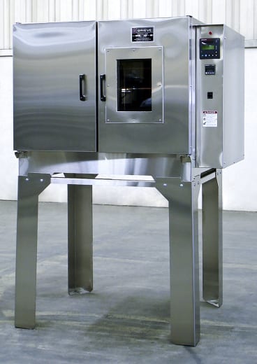 No. 1017 is a 1000ºF high-temperature bench oven from Grieve, currently used for various heat processings at the customer’s facility. Workspace dimensions of this oven measure 22” W x 22” D x 13” H. 3 KW are installed in Incoloy-sheathed tubular elements to heat the oven chamber, while a recirculating blower provides airflow to the workload.
This Grieve bench oven features 5” insulated walls, stainless steel exterior with #4 brushed finish, Type 304, 3B finish stainless steel interior, integral oven stand and an 8” x 10” double-pane Pyrex/Vycor viewing window.
Controls onboard No. 1017 include a digital programming temperature controller and manual reset excess temperature controller with separate control contactors.
For more information, please contact:
THE GRIEVE CORPORATION
500 Hart Road
Round Lake, IL 60073-2835 USA
Phone: (847) 546-8225
Fax: (847) 546-9210
Web: www.grievecorp.com
Email: sales@grievecorp.com
Attention: Frank Calabrese
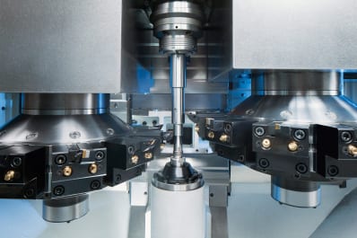
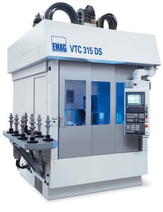 The advantages for the user are obvious. In the past, it was necessary to decide in favour of one of the three technologies. Now, with the VTC 315 DS, it is possible to choose the technology that best suits individual applications. Dr. Guido Hegener, the executive responsible for grinding technology at EMAG Salach Maschinenfabrik GmbH, comments on the diverse applications: “We are consistently following the path of combination machining. As a rule, our customers manufacture different workpieces on the machine. We intend to offer them the best technology for every application.” The VTC 315 DS is of interest to those engaged in the manufacture of medium and large batches of high-quality components such as gear shafts, rotor shafts, pump shafts, motor shafts or cardan shafts. The machining technology is chosen accordingly. Sturdy workpieces are machined using the scroll-free turning technology. The grinding technology is preferred for smaller, less stable components. “This makes us more flexible and allows us to choose the right technology for every individual requirement”, explains Dr. Guido Hegener the advantages. The machine can be used as a fully-fledged grinding machine, or a fully-fledged turning machine, or a combination of both. When choosing a technology one should take a closer look at the cycle time and, in particular, at the tooling cost. Unit production costs are usually higher with hard turning and scroll-free turning than with grinding, although CBN grinding wheels – in absolute terms – are rather expensive. It is for this very reason that the user has to decide on a case by case which manufacturing technology to use.
Different technology modules for different workpieces
 The developers of the VTC were also considering the machine as an investment in the future. Should production requirements change, the machine can be equipped – at very little expense and effort – with different technology modules that make it suitable for machining of the new workpiece. At present, the technology modules available are:
This guarantees flexibility in the use of the machine and opens up a wide range of applications, especially as all the technologies can be applied also in combination.
VTC production lines
The VTC 315 DS is ideally suited for complex manufacturing processes. Whether the job includes the high metal removal rates of turning and milling or the gentler grinding process – the VTC series of machines offers the possibility to integrate most of the metal cutting processes. This allows for the creation of complete VTC production lines for soft and hard machining. Turning, milling, drilling, grinding and gear hobbing have already been modularised for this particular machine platform. It provides the VTC with an extensive field of application. “We have already installed complete production lines of VTC machines for the soft machining of crankshafts. Almost all of the operations could be accommodated on machines from the VTC series”, this is how Markus Woitsch, chief of the production team for shaft machines, explains the production line concept of the VTC. Naturally, subjects like spare part stocks and unified machine operation also play a decisive role in the eye of the customer. With a production line that interlinks a number of different VTC machines and utilises different manufacturing technologies, spare part stocks can be drastically reduced, as 80% of the VTC machine components are the same. Only the technology modules change, when a VTC has to be adapted for a new machining requirement. 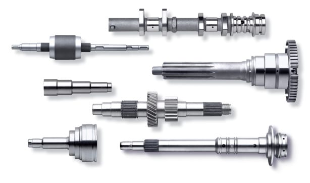
Complete-machining through technology combination
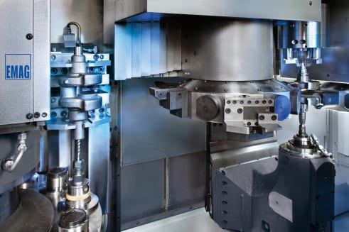
The VTC 315 DS accommodates turning as well as grinding technologies. For example, the turret carries out all turning operations, while the second station is used for the grinding work. This way, shafts can be complete-machined: the cylindrical bearing seats, the shoulders and the grooves – all machined in a single set-up. “Clamping errors play a particularly important part when it comes to high-performance components. Radial runout can be much reduced when a workpiece does not have to be re-clamped several few times”, elucidates Dr. Guido Hegener on the quality of the machine. To keep downtimes caused by tool changes to a minimum, sister tooling is provided for all turning operations. And the tool life of grinding wheels is so high that the time taken up by a wheel change is of no consequence.
The VTC 315 DS design
A distinguishing feature of the VTC 315 DS is its sturdiness and rigidity. At its heart is the machine base in Mineralit® (polymer granite). The damping properties of this material is 8 times that of grey cast iron, which makes it particularly well suited for hard machining operations like grinding or hard turning. The results are improved tool life and a better surface finish. The vertical design also aids unhindered chip flow. Manual removal of chips is hardly ever necessary. This is particularly important in soft machining, as it often involves volume-intensive chipping operations. The vertical construction is also of advantage where the footprint is concerned. Machines with horizontal spindle and tailstock take up a lot of space width-ways. That raises floor space requirements and costs money. Vertical machines develop upwards, and that – as we know – costs nothing. Automation on the VC 315 DS lies in the turret. A gripper, housed in the turret, collects the raw-part from its storage section and transfers it to the clamping position. Once the workpiece is machined, it is transferred out of the machine the same way. And thus the machine automates itself. The generously dimensioned machine assemblies, such as the work spindle with 330 Nm constant torque, and the grinding spindle with a power rating of 30 kW, have so much reserve capacity that even heavy metal removal work can be carried out on the machine. The control system used is a Siemens 840 D with EMAG grinding software that simplifies programming and operation.
The advantages of the VTC 315 DS:
For more information:
EMAG LLC
38800 Grand River Avenue
Farmington Hills, MI 48335
Tel: (248) 875-0313
Fax: (248) 477-7784
E-mail: info@usa.emag.com
Web: www.emag.com
Attention: Peter Loetzner

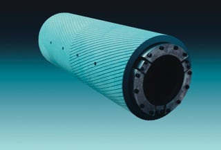
Kastalon engineers match assorted textured surfaces and material hardnesses to the application.
Kastalon offers mills and processors highly engineered polyurethane mandrel sleeves, filler plates and filler rings with material hardness and surface options to match customer needs, protecting coils from damage
Kastalon brings 50 years experience in coil processing to the task of engineering a new offering of application-specific, proprietary formulated polyurethane mandrel sleeves, filler rings and filler plates. These products are designed to adapt the mandrel to handle coils with larger ID’s and addresses the problems of damage from creasing, scratching and marring at mills, service centers, toll processors and fabricators alike. Such damage is expensive for any coil handling operation, especially when the metal is prepainted or must maintain optimum cosmetic surface integrity. By the use of Kastalon mandrel sleeves, filler rings or filler plates on the uncoiler or recoiler, the inside wraps on coils are protected from metal to metal contact. More finished material is produced or usable, as a result.
Mandrel sleeves are custom designed with engineered surface hardnesses and grooved or smooth finishes, depending on the particular application. Full sleeves are usually recommended for the recoilers, while filler rings and filler plates are more often utilized for uncoilers.
The design process begins at the company website, where a detailed needs-assessment questionnaire can be completed, followed by a discussion with Kastalon engineering to formulate the proper chemistry, surface and material hardness for the application.
In use, the proprietary chemistry of the Kastalon Polyurethane material withstands the stress caused by the weight of the coil, then reforms when the mandrel is collapsed back to the rest position, owing to the inherent memory of the Kastalon engineered material. With other materials now on the market, sleeves will often sag due to memory loss and the resulting gap can cause significant coil damage. Correspondingly, additional labor and line downtime result from this condition, as realignment of the coil, sleeve and mandrel is needed. Through the true and precise sizing of the mandrel sleeve, combined with the proper material hardness and surface texturing, a Kastalon sleeve can last up to 10 times longer than rubber, fiber or even other commodity type polyurethane products, according to company research, available on request.

Mandrel sleeves, filler rings and filler plates allow coil processing to be accomplished more efficiently, whether on uncoil or recoil reels, at mills, service centers, toll processors and fabricators.
Kastalon mandrel sleeves are non-marring, cut-resistant, abrasion-resistant and offered for friction fit, requiring a separate “keeper”, or bolt-on installation. Company engineers consult customers on the amount of lubricant, cleaning solution or other coating chemistries present in the process, as this will determine the particular formulation selected. Furthermore, Kastalon offers these mandrel sleeves in a wide variety of grooved or soft surface finishes to meet the specific tension and pressure requirements of a processor’s uncoil/recoil apparatus. Special dual-durometer sleeves are also available for mills and processors where “head-in” damage is often encountered.
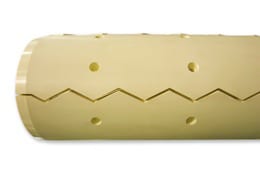
Kastalon engineers match assorted textured surfaces and material hardnesses to the application.
For most uncoilers, Kastalon filler rings or filler plates can provide the optimum performance for the tension, pressure and metal contact requirements typically present.
The design process for Kastalon mandrel sleeves can begin with a visit to the company’s website, www.kastalon.com, for completion of a needs assessment questionnaire. Detailed information is gathered on this form, allowing the Kastalon engineers to calculate the best sleeve design and chemical composition to suit the job.
For more information on this product, please contact:
KASTALON, INC.
4100 W. 124th Place
Alsip, IL 60803
Phone: 708-389-2210
Fax: 708-389-0432
Web: www.kastalon.com
Email: sales@kastalon.com
Attention: Marty Pokorney
Tessy Plastics uses virtual process development software to simulate the entire injection molding process before production, enabling them to expand their global presence while finding the most cost-effective and high-quality manufacturing solutions.
Tessy Plastics was founded by Henry Beck in 1973 and is headquartered in Central New York with facilities in Virginia and China. Tessy is constantly expanding their global presence in order to find the most cost-effective and high-quality manufacturing solutions. Producing everything from intricate medical devices to everyday consumer items, Tessy strives to engineer, manufacture, assemble and distribute products in the most effective and profitable way possible for their customers. As a family-owned and operated, privately held company, Tessy positions themselves as their customer’s manufacturing partner, taking ownership and a proactive approach on every project they encounter.
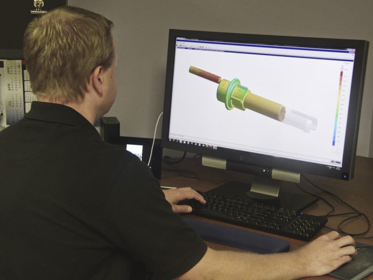
Stafford Frearson, Project Engineer at Tessy Plastics, works on a project using SIGMASOFT at Tessy Plastics in Elbridge, NY.
Servicing the medical, consumer products, business machines, electronic and packaging markets, Tessy partners with their customers from the design stage all the way through product completion. Enabling them to provide their customers a full service experience, Tessy offers additional services including ultrasonic, vibration or laser welding, hot stamp/hot decal, pad printing, laser engraving, or label application printing, manual, semi-automated, fully automated or cleanroom assembly. Finishing options include gluing/bonding, machining/drilling, contact insertion, as well as, high-speed fluid dispensing or ultrasonic dispensing. Tessy also provides leak, burst, dielectric, electric, optical, rheological and spectrophotometer testing. As part of their partnership, Tessy holds themselves 100% accountable for quality assurance.
Proud of their “Commitment to Innovation,” Tessy is in constant evolution creating an atmosphere of growth and discovery. Joe Raffa, VP and General Manager in charge of sales, says, “Using our engineering department, our goal is to continually explore and implement new ways to enable our customers to significantly evolve their business in the most cost effective, lean manner .” Tessy is keeping the injection molding process on the cutting edge of technology by having the capability to evaluate the entire process virtually before sample runs are even attempted on the shop floor. Eric Frearson, VP of Engineering, states, “We have some very complex parts that we manufacture as well as complex molds. Acquiring SIGMASOFT® about two years ago to virtually run the entire mold and process before using production time changed the way we do business. This enables us to understand and find solutions to significant problems that, in some cases, we have been working on for a long time,. We are now pointed in the right direction and shown the precise areas we need to focus on to create a solution, thanks to this process optimization software package.”
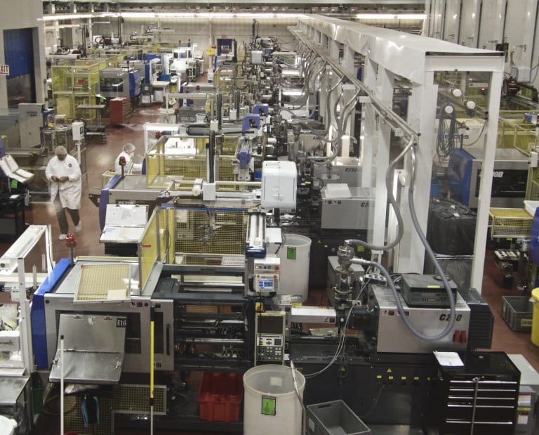
One of the cleanrooms at Tessy Plastics in Elbridge, NY.
At Tessy, the members of the sales team have engineering backgrounds while the engineering team is heavily involved in building, developing and maintaining customer relationships. The sales team boasts trying to commit the engineers to projects that are almost impossible while the engineers welcome the challenge and come up with ways to make them happen. Raffa explains, “With SIGMASOFT® onboard, we are able to commit to these almost impossible jobs. I know that when the customer poses new projects to us, I can go to engineering and talk about warp analysis or filling analysis and whether or not a project is even feasible. Once getting that confirmation after running the process virtually, I have the confidence to commit to a project, knowing that the information we received from the simulated run will reflect reality at least 98% of the time.” Matt Learo, Sales Manager, adds, “We had an existing customer where the materials they were using were discontinued. The customer called and requested that their new material and new tool be run through SIGMASOFT® specifically, to see how the new material was going to behave.” Stafford Frearson, Project Engineer expands, “The more complicated a project is and the more complex a configuration might be, when we are not sure how it might warp or how it might fill, there’s no question we feel more confident in going to the customer and saying, ‘this is what you are going to see’, when we have the report backing us up.” “We use other simulation software, but when the part is complex and on our harder jobs, we always run them through SIGMASOFT®,” Eric Frearson adds.
Tessy has used simulation software for over 20 years but feels adding SIGMASOFT® as one of their resources significantly changed the way they do business. Raffa told of a situation that occurred within the first few months after acquiring the new software. Most new projects Tessy acquires are first-time molded products. In most cases, Tessy helps design the part as well as the molds. Normally, all the components in the assembly are new designs. In one particular instance that Raffa described, the customer wanted to take new components and marry them to old components for a different look in the end product. Tessy learned by examining the way some of the wall thicknesses had to be designed and the way the assembly had to come together through simulation that it wasn’t optimal and the new design would simply not work. The parts that were being received from the prototype molds found warp that Tessy had never seen on these types of projects previously. The customer requested a stress and distortion analysis from an engineering company, costing them thousands of dollars, in addition to taking considerable time. Although the engineering company did provide some results and recommendations, the evidence to support these recommendations was not provided.

Eric Frearson, Vice President of Engineering, Tessy Plastic (Left) and Stafford Frearson, Project Engineer at Tessy Plastics, discuss a SIGMASOFT screen at Tessy Plastics in Elbridge, NY.
This became the first large project on which Tessy used SIGMASOFT®. By running multiple processes and cooling times and looking at iterations even 24-48 hours later to see how the part was going to react, it was clearly seen when pulling up snapshots and data during certain points through the process what the issue was. Tessy was able to see the part, how it cooled outside of the mold, how it flexed and how it actually got to the state where it was warped. Eric Frearson said, “It gave us evidence to show the customer that no amount of cooling changes or process changes had any effect on the problem. It was purely a design change that was needed to fix the problem. The reports provided by the software gave us the credibility and the client the reassurance to make the changes.” Raffa adds, “It essentially short cut the entire process, we didn’t try running DOEs of all different configurations or measured a ton more parts to chase something that was really not the solution.” Learo also states, “What’s reassuring about this situation was that we hadn’t used SIGMASOFT® for very long at this point and the customer was willing to pay for the stress and distortion analysis from the engineering company and see how the results compared. We found the results long before the engineering company did. When we did receive their findings, they were the same. The difference was, we were able to show why it happened and already had a solution to present our customer.” Eric Frearson adds, “Even the engineer running the analysis at the independent company was impressed. He is an experienced analyst who regularly uses a different product.”
Tessy uses virtual scientific injection molding almost exclusively, enabling their customers to save time, material and money by doing virtual studies in order to predict molding parameters. The addition of this valuable tool enables them to focus on what the final process would be. “We can now say with a very high degree of certainty what the cycle times will be and what issues we might have, before manufacturing ever sees the tool. We weren’t able to say that before having SIGMASOFT®,” Raffa said. Tessy also sees an impact of the software on manufacturing, by helping validate the process before a mold is cut. Learo adds, “We are able to give the process technicians better process parameters before we even see the mold.”

Matt Proske, Vice President, SIGMA Plastic Services (Left) and Stafford Frearson, Project Engineer at Tessy Plastics, have a conversation at Tessy Plastics in Elbridge, NY.
Giving credit to their “Commitment to Innovation,” Tessy is experiencing record growth and expansion in their business, even in these unstable economic times. The implementation of innovative technologies continues to not only ensure profitability, but also contributes to its employees’ ability to further their careers, providing opportunities for advancement on multiple levels. Being part of an industry that is constantly evolving, the leadership at Tessy keeps encouraging their team to reach the highest standards and quality deliverables, which in the market drives all plastic molders to move forward and continue to reach out for new and more efficient ways of serving their customers. It is Tessy’s goal to strive for the most cost-effective, time-saving solutions to ensure quality products for its partners.
For more information, contact:
Matt Proske
Vice President
SIGMA Plastic Services, Inc.
10 N. Martingale Road, Suite 425
Schaumburg, IL 60173
Phone: 847-558-5602
Email: contact@3dsigma.com
Web: www.3dsigma.com
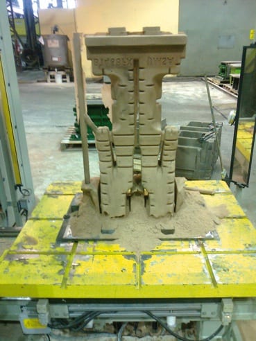
Figure 1. First Core Blowing Test. The bottom of the core collapsed due to a lack of strength.
Brazilian steel giant Usiminas recently introduced the new foundry core making simulation software MAGMASOFT® as part of their strategy to establish robust designs and processes for their core production line. The first project on which this software was utilized was already in progress at that time.
The main goal was to optimize the process conditions for the existing tooling layout. This core, called the thin waist core, represents some of the biggest challenges for Usiminas core production: its length (920 mm), substantial changes in the sand flow direction during blowing, the need to fill certain parts of the core through counter-flow and big variations in the cross section within the core.
First trials showed problems with the process, which led to a complete collapse of the lower part of the core. The core blowing and curing steps for the PU coldbox process were analyzed, making it possible to draw preliminary conclusions regarding the existing defects.
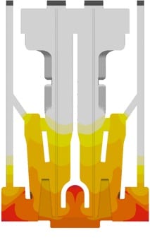
Figure 2. Curing Gas Concentration. The curing gas does not penetrate into the core to the same extent everywhere.
The lack of core strength was related to a poor curing process. The first simulation (Figure 2) already showed that the problematic regions experienced only very low curing gas concentrations during gassing, which was the root cause for the failure.
On the production line, various process conditions such as the curing and purging times and gassing pressure were changed. These attempts provided better results (Figure 3). However, a perfect core could still not be produced. The further analysis with MAGMASOFT® focused on the evaluation of the local concentration of adsorbed curing gas, as it shows the regions where the catalyzing gassing agent cannot activate the chemical reaction. This result clearly demonstrated that only a very small quantity of catalyst was available for accelerating curing in the defect regions (Figure 3).
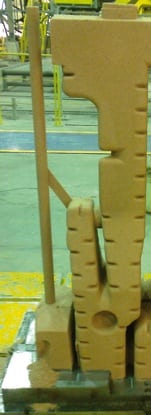
Figure 3. Core Blown with new parameters in comparison with the local concentration of adsorbed curing gas. The problematic area corresponds exactly with low concentrations in the simulation.
Evaluating simulated curves for the gas mass flow through the vents made it clear that the catalyzing gas was not reaching the critical area. The open venting cross section of the top and central vents was allowing the gas to escape before it reached the bottom of the core.
Instead of making costly modifications to the core box, Usiminas determined that a possible – and simple – solution was to close some vents in the top and center regions, in order to increase the gas concentration in the bottom. However, it was clear that these changes obviously would also influence the core blowing step.
The optimization led to a considerable increase of the curing gas concentration in the lower regions of the core (~36%) (Figure 4). Also, the amount of adsorbed curing gas increased in comparison to the original project. Applying these modifications, Usiminas produced another core, which did not show any gassing defects. Since the venting area was reduced, some filling defects were present, as expected.
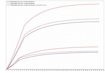
Figure 4. Total gas mass flow through the lower vents. The change in mass flow becomes clear. Removing some of the upper and middle vents resulted in a 36% increase in the gas escaping through the lower vents.
Having solved the curing related defects, a further core blowing analysis was carried out. The simulation results showed a very good match between the real defects and areas of low packing density. The flow animation also showed that the problems occurred because these areas had to be filled by a counter flow of the sand (Figure 5).
Another characteristic of the defects was that they all occurred next to the parting line of the core box. Some of the defects showed a smooth surface, indicating that the sand had been removed by a strong air flow. The core blowing simulation results supported the Usiminas conclusion that an improper sealing of the tool was the root cause for these defects. Air could escape with high speed through the parting lines, resulting in the defect formation.
This hypothesis was tested using a silicone rubber band to obtain an improved sealing of the relevant areas of the tool. With this modification, a new core was produced which was absolutely free of any defects.
About software for casting process simulation
Casting process simulation software considers the complete casting process including mold filling, solidification and cooling, and also provides the quantitative prediction of mechanical properties, thermally induced casting stresses and the distortion of cast components. Simulation accurately describes a cast component’s quality upfront before production starts, thus the casting layout can be designed with respect to the required component properties. This results in a reduction in pre-production sampling, but also the precise layout of the complete casting system leads to energy, material and tooling savings for the foundry.
The range of application of MAGMA solutions comprises all cast alloys, from cast iron to aluminum sand casting, permanent mold and die casting up to large steel castings. The software supports the user in component design, the determination of melting practice and casting methodology through to mold making, heat treatment and finishing. This saves costs consequently along the entire casting manufacturing line.
During the last 10 years, the use of casting process simulation has become a valuable business asset for many foundries worldwide. MAGMA5 constantly expands the capabilities of casting process simulation and will further accelerate the acceptance of this technology, in the future.
About Usiminas
With 50 years of operation, Usiminas is the leader in the Brazilian flat steel market and one of the largest steel companies in Latin America. It has a nominal capacity of 9.5 million tons of steel per year. Usiminas Mecânica is a leading provider of capital goods and services to the steel, railway, mining, automotive, energy, petrochemical, marine and infrastructure industries in Brazil. With recent substantial investments, the foundry of Usiminas Mecânica has become one of the largest manufacturers of both small and large steel castings in the country. The yearly production capacity is 30,000 tons, representing about 10% of the projected production in Brazil.
About MAGMA
MAGMA offers comprehensive solutions to the metal casting industry, casting buyers and casting designers worldwide. The MAGMA product and service portfolio includes the powerful modular simulation software MAGMASOFT®,with the newest release MAGMA5, as well as engineering services for casting design and optimization.
Today, MAGMASOFT® is used throughout the metal casting industry, especially for the optimization of cast components in automotive and heavy industry applications.
MAGMA Giessereitechnologie GmbH was founded in 1988 and is headquartered in Aachen, Germany. A global presence and support are guaranteed by offices and subsidiaries in the USA, Singapore, Brazil, Korea, Turkey, India and China. Additionally, more than 30 qualified partners represent MAGMA around the world.
For more information on this release, please contact:
Christof Heisser
President
MAGMA Foundry Technologies, Inc.
10 N. Martingale Road, Suite 425
Schaumburg, IL 60173
Phone: 847-969-1001 ext. 225
Email: cheisser@magmasoft.com
Web: www.magmasoft.com
CAROL STREAM, ILLINOIS – The demand has never been greater for specialized supply chains that deliver medical materials to meet the production demands of OEM’s. These businesses are acutely aware of the need to use quality metals and materials in their products to assure performance, durability and long-term reliability. Due to the recent revisions to ASTM standards F136 and F138, Banner Medical has installed a multi-axis, computer controlled Ultrasonic Inspection System designed and built by Matec Inspection Companies, Inc., for precision ground bars.
ASTM F136 and ASTM F138 are commonly specified standards in the design of titanium and stainless steel surgical implants; and recent revisions to each standard call for ultrasonic testing at final diameter for all centerless ground, or peeled and polished bars, which are greater than or equal to .375” in diameter.
“The decision to purchase this highly versatile inspection system was driven by the current and future needs of our customers. We are experiencing greater demand for ultrasonic testing of medical grade raw materials and the recent changes to ASTM standards F136 and F138 will increase demand even further in the very near term,” said Bob Khin, Vice President of Quality Assurance, Banner Medical.
“We recognize the impact these revisions will have on our customers. Ultrasonic testing at final diameter has the potential to add significant delays and cost to the supply chain. Our new ultrasonic inspection unit allows us to ensure the precision of centerless grinding and testing under one roof. We are providing our customers with a cost effective, time saving solution to the problems which could arise as manufacturers begin to comply with these changes. We will maintain the inventory, production capability, and testing equipment in a medical focused factory,” said Dan Stoettner, Executive Vice President and Chief Operating Officer.
To fully comply with industry testing standards, Banner Medical has hired additional qualified personnel to operate the equipment and implement the proper management systems including Rick Wallen, Director of Technical Services. He will assume full responsibility for the ultrasonic testing program. Rick was employed at Zimmer Inc. for 34 years in various roles and most recently served as Principal Engineer, Quality. He was responsible for all nondestructive testing requirements company-wide.
“We feel very fortunate to have Rick join our team. He is an industry recognized expert in ultrasonic testing and Quality Management Systems, and we are certain he will make an immediate impact within our organization. Rick is an ASTM certified Level III Engineer and an ASQ certified Quality Auditor. He is going to help us provide the very best service to our customers,” said Bob Khin.
###
Banner Medical serves the medical device, implant, and instrument industry with medical-grade metal materials; Banner Medical is ISO 13485 and ISO 9001 certified, and FDA CFR part 820 compliant.
For more information:
BILL NORLANDER
Medical Products Specialist
494 East Lies Road
Carol Stream, IL 60188-9425
P:630.868.1230
F:630.653.7555
E: bnorlander@banner-medical.com
www.banner-medical.com
MIKE HADLEY
Supply Chain Manager
494 East Lies Road
Carol Stream, IL 60188-9425
P:630.868.1229
F:630.653.7555
E: mhadley@banner-medical.com
www.banner-medical.com
The International Monetary Fund (IMF) estimates that the world economy will grow by 3.5 percent this year, with the impetus coming less from Europe and more from dynamic, newly industrialized countries. One example is the automotive industry. According to the association for the German automotive industry (VDA), China’s share of the market in passenger cars increased by 59% and that of Brazil by 18% during the first few months of 2013. The same market is also growing in India and Russia. For a long time, new production facilities have been planned and are under construction, providing great opportunities for the machine tool industry – as the example of EMAG proves. Specialists are developing turnkey manufacturing systems that are tailor-made to suit specific market conditions, with the new production facilities in particular gaining substantially from this increased market activity.
 Whether in the automotive or energy supply industry, the development of industrial key sectors within the BRIC countries (Brazil, Russia, India, China) has a direct influence on the machine tool industry, as it is this branch that, in the end, must supply most of the necessary manufacturing solutions. There are numerous indicators for this fact. For instance, according to Germany Trade and Invest (GTAI), the Russian enclave of Kaliningrad will – over the next 3 years – will see an investment of 3 billion Euro in six assembly facilities and fifteen sub-supply companies for the national automotive industry, with more international sub-suppliers also establishing outlets in the market. Similar activities are reported from Brazil. According to Anfavea, the country’s automobile association, approximately 22 billion USD are to be invested in production between now and 2015. In India, economic growth is generally attracting “an abundance of investment projects in the country’s infrastructure, as well as in new industrial complexes,” states GTAI.
 The German machine tool industry is prepared for such a dynamic development and the opportunities it provides can be seen in the textbook case of EMAG. Their specialists see themselves as “partners in solutions” for the metalworking industry. Such an approach is of great importance, especially in the emerging markets. “As it happens, we don’t just deliver a machine tool. We deliver closely pinpointed manufacturing solutions that are, in every respect, tailor-made to customer requirements”, explains Dieter Kollmar, Managing Director of EMAG Holding GmbH. “This applies, of course, to typical factors such as batch sizes, component variants or, more generally, the flexibility of the processes applied. At the same time, we determine locally the technologies, automation equipment, interfaces and control systems required.“ The advantages for the customer are obvious, especially where an existing production line is extended or where a greenfield manufacturing facility must be created in a new market place. Our manufacturing systems are always “from a single source.” Even complex processes with peripheral machines and equipment are presented as turnkey projects by EMAG, thus considerably reducing the efforts of local production planners.
VL 2: Highly effective, truly outstanding space saver
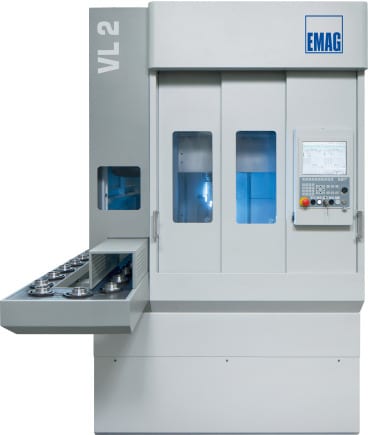 The VL 2 is a pick-up turning machine with which the EMAG engineers are fulfilling a combination of two extreme demands: highest possible output rates on the smallest possible footprint. “This is a truly all-important aspect,” confirms Dieter Kollmar. “Although the floor space requirement for this vertical turning machine is just about 5 square meters, it is a machine of substantial capability, including a fully comprehensive automation concept with conveyor belt, workpiece storage and pick-up spindle. In combination with vertical turning, this results in very fast machining processes. “In other words, short loading travel guarantees the lowest possible component cost. Compared to horizontal turning machines, productivity rates increase quite noticeably. And maintaining the VL 2 is simple. All service units are freely and quickly accessible. The user can set up the machine in one step. “That too is important, when productivity levels enter the equation. Operators without prior experience, working at a new and unfamiliar location, will be able to quickly familiarize themselves with the machine. All in all, this is an optimal solution for those who want to extend production with as little investment as possible,” notes Kollmar.
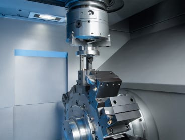
VT 2-4: For demanding shaft production
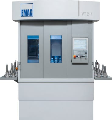 A similar approach is shown with the VT 2-4 Vertical Turning Machine, with which the EMAG specialists have created an equally fast manufacturing system for shaft production. Even demanding machining processes can be realized on it. When machining shafts up to 400 mm length and 63 mm diameter, component costs reduce considerably, with extremely short chip-to-chip times (as with the VL 2) being the reason. Workpiece grippers transport the workpieces into the machine and remove them again, once they have been machined. Depending on the workpiece, the changeover can be accomplished in just 6 seconds. And the actual turning process is fast, too. 4-axis machining allows the component to be machined from two sides simultaneously. Vertical alignment of the workpieces provides consistent process integrity, as the unrestricted chip flow prevents the formation of clusters in the machining area.
Central project management
 “We are convinced that these EMAG solutions are optimally designed to cover not only the specific requirements of an emerging market, but also those of Europe and the USA,” as Dieter Kollmar his company’s philosophy. Everything is greatly simplified, starting with production planning, as there is no need for separate workpiece and finished component storage, with the added advantage of a reduced floor space requirement. At the same time, the EMAG Group engineers act as central project developers, having access to machines with optimal interfaces. This guarantees a fast run-in and makes the machines maintenance-friendly. “When it is a question of arriving quickly at a wholly integrated, highly effective manufacturing solution, this approach must – from our point of view – be the first choice,“ Kollmar concludes.
For more information, please contact:
Kristal Kilgore
EMAG LLC
38800 Grand River Avenue
Farmington Hills, MI 48335
Tel: (248) 875-0313
Fax: (248) 477-7784
E-mail: kkilgore@emag.com
Web: www.emag.com
CAROL STREAM, ILLINOIS — Firth Rixson Metals, a global leader in specialty metals manufacturing and distribution based in the United Kingdom, and Banner Medical, a leading provider of supply chain solutions for medical-grade materials to the device, implant, and instrument industry, announce their exclusivity agreement for sales and marketing for Cobalt Chrome in the United States, effective January 1st, 2014.
“The medical-grade metal materials that Firth Rixson Metals produces are of the highest standards. By combining this offering with Banner Medical’s expertise in quality assurance, we will meet the stringent demands of the medical industry,” stated Elinor Oldroyd, GM of Firth Rixson Metals.
“Banner Medical specializes in medical-grade materials and offers deep expertise in the quality management that is necessary to fully comply with FDA 21 CFR 820. The depth, breadth and detail of Banner’s approach to quality management and supply chain management is unique and that distinction justifies the patent-pending status of Banner’s Essential Quality Systems,” says Banner Medical Executive Vice President / Chief Operating Officer Dan Stoettner. “Firth Rixson shares our commitment to vigilance and quality in both products and service.”
The Firth Rixson-Banner Medical agreement focuses on the Device industry’s need for precision-ground cobalt chrome materials. Stoettner went on to say, “Given the importance of cobalt chrome to today’s device, implant and instrument industry, we strongly believe that the Firth Rixson-Banner Medical alliance can help our customers realize true supply chain control on Cobalt Chrome materials, making them able to effectively address the unprecedented FDA scrutiny which exists today in the United States.”
—
![]() Firth Rixson’s technological and operational excellence, combined with the firm’s economies of scale, has made the company the metals provider of choice for demanding customers in diverse specialized industries in more than 40 countries.
Firth Rixson’s technological and operational excellence, combined with the firm’s economies of scale, has made the company the metals provider of choice for demanding customers in diverse specialized industries in more than 40 countries.
![]() Banner Medical serves the medical device, implant, and instrument industry with medical-grade metal materials; Banner Medical is ISO 13485 and ISO 9001 certified, and FDA CFR part 820 compliant.
Banner Medical serves the medical device, implant, and instrument industry with medical-grade metal materials; Banner Medical is ISO 13485 and ISO 9001 certified, and FDA CFR part 820 compliant.
For more information:
BILL NORLANDER
Medical Products Specialist
BANNER MEDICAL
494 East Lies Road
Carol Stream, IL 60188-9425
P: 630.868.1230
F: 630.653.7555
E: bnorlander@banner-medical.com
MIKE HADLEY
Supply Chain Manager
BANNER MEDICAL
494 East Lies Road
Carol Stream, IL 60188-9425
P: 630.868.1229
F: 630.653.7555
E: mhadley@banner-medical.com
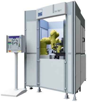
VA 700 T – Joining machine for the manufacture of composite camshafts. While one cam is heat shrinking, the next one is preheated. Equipping the heat shrinking machine with a number of preheating units allows for the optimal application of this technology to suit the task at hand.
The composite camshaft is still gaining ground in the marketplace. The main reason for this is the considerable weight reduction it brings, compared to its one-piece rival. The composite version is by now also widely used in the HGV sector. However, the main disadvantage of many current assembly processes is the high joining force applied, which creates unacceptable tolerances in positioning and alignment of the cams. By contrast, the patented heat shrink assembly process from EMAG offers a decisive advantage, as it ensures that “ready-to-fit” camshafts, gear shafts and other precision composite units can be produced without problems.
The advantages of the composite camshaft are well known: less expense, less weight, the possibility to use different materials for the various constituent components, greater flexibility in production and the ability to implement new cam geometries, such as negative radii, with ease. The necessary reduction in fuel consumption – and with it those of CO2 emissions – are easier to achieve with an increasing use of composite camshafts.
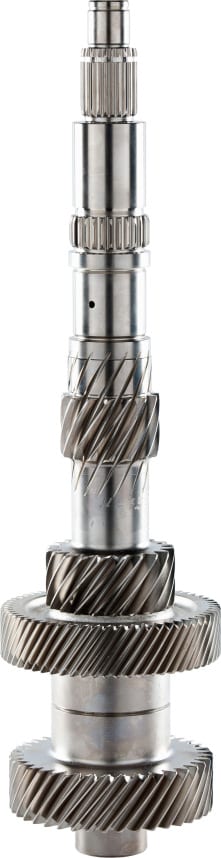
Also used for gear shafts, heat shrinking of the constituent components ensures a compact design and high functional density, as the gears are in direct contact with the shoulders.
Alternative processes for the joining of cam and shaft have one serious disadvantage: the two components cannot be joined with the necessary accuracy to avoid a subsequent finish grinding process. In many cases, the joining of cam to tube is carried out using a form-fit process like press-fitting, knurling and/or spline/serrated gearing. The joining forces required for these processes can deform the components and result in unacceptable tolerances in cam position and orientation.
The heat shrink assembly process from EMAG means precision joining
Thermal joining, i.e. the heat shrinking of cam onto tube, ensures that the required tolerances are achieved with a reaction force-free process. The know-how to tightly control the process parameters of “temperature” and “time” – and the mechanical design of the joining equipment – are of the utmost importance in this process.
An optimal combination of robot and special-concept gripping technology allows for fusion gaps of < 15 µm to be achieved safely. The concept’s great flexibility allows camshaft designers more freedom in their designs and ensures that the process can also be used for medium batch sizes, where frequent component type changes are the order of the day. The high degree of precision of the composite camshaft drastically reduces the need to subsequently grind the cams or – where precision cams are used – does away with the requirement completely. A further advantage of this process lies in the possibility of using different materials for the composite shaft. This includes forged cams, for instance in 100Cr6, or finish-ground cams, even dimensionally accurate sintered cams that do not require a downstream finish-grinding operation. Secondary components, such as bungs and endpieces, can – just like the actual shaft itself – be made of more advantageous materials.
All this allows the camshaft to be made to suit the requirements of the engine and to optimize it in terms of load bearing capacity and manufacturing costs.
And now one step further:
Where the camshaft needs to be ground after heat shrink assembly, the joining machine can be linked up to a grinder. This is particularly easy when using an EMAG grinding center of the VTC DS Series. With this setup, the joining machine robot transfers the assembled camshaft directly to the loading position on the grinding center. The advantages of this process from EMAG also apply to the machining of other components. When machining gear shafts, ground gears can be joined tightly on the shaft, without needing to account for the grinding wheel overrun at the design stage. It also minimizes the length of the shaft and makes the whole unit more compact.
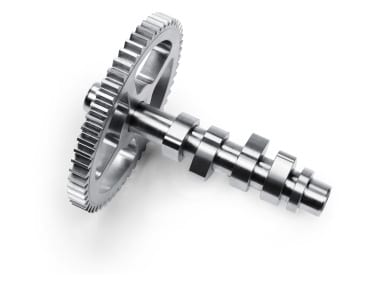
Ready-to-fit, complete, heat shrunk assembled camshaft. The high degree of precision of the composite camshaft drastically reduces the need to subsequently grind the cams or – where precision cams are used – does away with the requirement altogether.
Maximum flexibility
The EMAG process is characterized by only a very few machining components being in direct contact with the workpiece. It allows for the machines to be reset in the shortest possible time (typically less than 15 minutes).
Joining in seconds and achieving the highest possible quality
The heat shrink assembly process offered by EMAG combines flexibility with productivity, while freedom of design and choice of production technologies ensure a short cycle time. While one cam is heat shrinking, the next one is already being preheated. Equipping the heat shrinking machine with a number of preheating units allows for the optimal application of this technology to the task at hand. It is these advantages that may well be the reason why so many firmly established manufacturers of camshafts and other precision assemblies are showing such a great interest in the new process, are asking for machining tests, or are already applying the process under actual production conditions. In the ideal case, the customer will take advantage of the synergy provided by the EMAG Group and ask for a complete concept to be prepared that covers everything from pre-machining to heat shrinking and end machining.
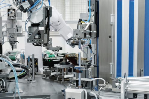
Finished assembly of a motorcycle camshaft. An optimal combination of robot and special-concept gripping technology allows the pieces to join with a fusion gap of
The advantages of the heat shrink process:
The advantages of the composite camshaft:
For more information, please contact:
Kristal Kilgore
EMAG LLC
38800 Grand River Avenue
Farmington Hills, MI 48335
Tel: (248) 875-0313
Fax: (248) 477-7784
E-mail: kkilgore@emag.com
Web: www.emag.comEMAG LLC
38800 Grand River Avenue
Farmington Hills, MI 48335
Tel: (248) 875-0313
Fax: (248) 477-7784
E-mail: info@usa.emag.com
Web: www.emag.com
Attention: Peter Loetzner
Continue reading