Contact us today:
(847) 934-4500
tdaro@bernardandcompany.com

Contact us today:
(847) 934-4500
tdaro@bernardandcompany.com
Argus Subsea uses hydraulic rod locks from AME to secure underwater oilfield trees at 5000-6000’ depths to 3000 psi and 50,000 pounds of axial holding
Argus Subsea produces its AZ-10 fully concentric, vertical mono-bore subsea tree design for rapid field development. Originally designed for low net present value (NPV), marginal and smaller fields, where the capital investment containment is critical and the need exists for off-the-shelf hardware, the AZ-10 can be run on any rig, regardless of moonpool size or accessibility through a V-door or port side. Essentially, according to Earl Broussard, the company’s director of sales & marketing, “Anywhere a rig can power a BOP, the AZ-10 can operate effectively. And, being a standard horizontal tree design with a universal tubing hanger system that runs in any 18-3/4”, 10,000 or 15,000 psi wellhead, with a concentric design for all downhole and tubing hanger-to-tree interface, it can be quickly put into service.” In fact, the company’s literature boasts a typical reduction in time to first oil of fifteen months, with lower CAPEX and OPEX costs, less drilling and wellhead completion cost, plus reduced third-party cost.
The AZ-10 is currently rated at 10,000 psi working pressure and 6000’ water depth and is designed to the standards of API 17D, API 6A, PR2, NACE MR0175 and AV1 PR-2 USV. The unit weighs approximately 50,000 pounds and is light enough to be handled safely with rig cranes and easily transported to the moonpool. The AZ-10 can be deployed through any Generation-2 semi-submersible or newer generation rig’s moon pool. A much simpler design than most horizontal or vertical trees, the AZ-10 requires only five running tools versus 20-30 typically found on comparable subsea tree systems. The units are designed for 20 years of service life in production, injection or well test operations.
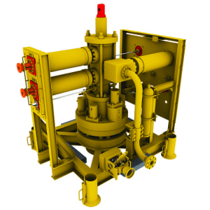
AMLOK rod lock highlighted on tree. Each rod lock operates to 3000 psi and provides 50,000 pounds of axial holding force at depths of 5000-6000’. Special construction, porting and heat treatment were utilized in the manufacture of these devices.
The hanger system operates on a lock and seal system that uses mechanical and hydraulic sealing within the tubing hanger. A key component designed into the AZ-10 is the AMLOK® hydraulic rod lock, provided by Advanced Machine & Engineering (AME) of Rockford, Illinois, a designer and builder of various rod locks for both hydraulic and pneumatic holding, in the event of a power loss. AME rod locks are typically found on all types of off-highway and construction equipment, as well as materials handling devices, machine tools and elsewhere, used to secure a cylinder rod in place to prevent further motion.
For the application on the Argus Subsea trees, according to Shane Hatfield, AME sales manager, several challenges were apparent and a few were not. The obvious obstacles were the depth and the pressures involved. The maximum load was to be 3000 psi and the axial holding force approximately 50,000 pounds at typical depths in the 5000-6000’ range. To address these issues, AME engineered the rod locks from 4140 steel with electroless nickel plating and a specially formulated two-part epoxy to create a completely sealed unit. Marine grade lubricant was used. “Those were the easy parts,” muses Hatfield.
With the external sealing system of the AZ-10 and the wide variety of connections involved, the construction of the rod lock also needed to accommodate the unique challenges of force over distance in a wide window of installation conditions. Since the customer was very cost-sensitive, it was necessary for AME engineers to create a one-size-works-for-all unit and this presented considerable application engineering challenges. “This was the hard part,” recalls Hatfield.
Working with Chance Burton, the driving force behind the original engineering effort at Azura, the predecessor company to Argus, Hatfield and his team demonstrated AMLOK rod locks as the only design that worked immediately over the entire range of performance scenarios. 1500 psi release and 3000 psi compressive were needed to satisfy all conditions and the AME engineers successfully satisfied these criteria. Key factors in the success of the AMLOK design here are the special porting and autoclave treatment used.
After an initial order of 10 units (2-4 used per tree), the business has remained steady, according to Hatfield. These rod locks have been used successfully on numerous installations of the AZ-10, where the connections to numerous wellhead equipment brands have varied considerably.
As the attached diagrams demonstrate, AME rod locks are actuated by a spring/collet mechanism upon loss of hydraulic power and unclamped by the restored pressure. They are built to accomplish a mechanical locking, holding a cylinder rod or machine shaft in position, up to the rated load, until power is restored and the locking mechanism released.
For more information on the subsea trees referenced in this story, please contact:
ARGUS SUBSEA 5510 Clara Road Houston, TX 77041 Phone: 713-983-7222 Fax: 713-983-7007 Email: info@argussubsea.com Web: www.argussubsea.com Attention: Earl Broussard, Director of Sales & Marketing
For more information on the rod locks referenced in this story, please contact:
Shane Hatfield, Sales Manager
ADVANCED MACHINE & ENGINEERING CO.
2500 Latham Street Rockford, IL 61103
Toll-Free: 800-225-4263
Phone: 815-962-6076
Fax: 815-962-6483
Email: shane@ame.com
Web: www.ame.com
AME-Advanced Machine & Engineering Co., is a manufacturer located in Rockford, Ill., serving the Machine Tool Industry with precision components and accessories, including spindle interface components, workholding devices and, through our sister company, Hennig, machine enclosures, chip removal and filtration systems. The Fluid Power – Safety markets are served with cylinder rod locks and Safety Catcher devices; and the Production Saw market with our AmSaw carbide saw machines and Speedcut blade products. AME has manufacturing partners and service centers around the world and across the U.S. To learn more, visit www.ame.com.
Hennig, Inc. designs and produces custom machine protection and chip/coolant management products for state-of-the-art machine tools. Hennig products are designed to protect against corrosion, debris and common workplace contaminants. Manufacturing facilities are located in the U.S., Germany, France, Czech Republic, Brazil, India, Japan, China and South Korea. Repair centers are located in Machesney Park, IL; Chandler, OK; Livonia, MI; Blue Ash, OH; Mexico City, Mexico; and Saltillo, Mexico. To learn more, visit www.hennigworldwide.com.
Please direct all inquiries from this article to:
Tim Waterman
ADVANCED MACHINE & ENGINEERING CO.
2500 Latham St.
Rockford, IL 61103
Phone: 815-316-5277
Fax: 815-962-6483
E-mail: info@ame.com
Connect with AME online:
Global leader in carbide sawing systems acquired by leading machine tool component and carbide saw machine manufacturer
Advanced Machine & Engineering (AME), the Rockford, Illinois-based manufacturer of various machine tool components and auxiliary equipment, today announced the asset purchase of the Metalcut Carbide Saw Division of Centro-Metalcut, also of Rockford and a longtime global industry leader in the design and manufacture of heavy-duty carbide sawing systems for the metalcutting industries.
AME is also a leading global manufacturer of carbide sawing systems, under its popular AMSAW® brand name. AMSAW systems are found in forge, metalcasting, service center and primary producer operations, anywhere large or continuous sawing is performed. The acquisition of the Metalcut carbide saw line represents a substantial expansion of the company’s capabilities in the world market.
This purchase will transfer the complete sawing machine technologies, engineering data, inventory, spare parts and service operations for all Metalcut carbide saws to AME. Steve Swanson, the business unit manager for the carbide saw machine division of AME, will assume oversight responsibility for the Metalcut product line, allowing a seamless transition for all existing customers and immediate access to the Metalcut carbide saw line for all new AME accounts. AME has worldwide sales and service locations already in place to accommodate all customer requirements, according to Greg Champion, vice president of sales & marketing for the company.
Centro-Metalcut will continue to manufacture and market all other product lines in its offering, including hot and cold abrasive saws, conditioning grinders and materials handling equipment.
Dietmar Goellner, AME president and CEO, and Danny Pearse, CEO of Centro-Metalcut, agreed to the purchase terms on September 24, 2010.
For more information, please contact:
Tim Waterman
ADVANCED MACHINE & ENGINEERING CO.
2500 Latham St.
Rockford, IL 61103
Phone: 815-316-5277
Fax: 815-962-6483
E-mail: info@ame.com
Connect with AME online:
Advanced Machine & Engineering Co., is a manufacturer located in Rockford, Ill., serving the Machine Tool Industry with precision components and accessories, including spindle interface components, workholding devices, and, through our sister company, Hennig, machine enclosures, chip removal and filtration systems. The Fluid Power – Safety markets are served with cylinder rod locks and safety catcher devices; and the Production Saw market with our AmSaw carbide saw machines and Speedcut blade products. AME has manufacturing partners and customers around the world and across the U.S. To learn more, visit www.ame.com.
Hennig, Inc. designs and produces custom machine protection and chip/coolant management products for state-of-the-art machine tools. Hennig products are designed to protect against corrosion, debris and common workplace contaminants. Manufacturing facilities are located in the U.S., Germany, France, Czech Republic, Brazil, India, Japan, China and South Korea. Repair centers are located in Machesney Park, IL; Chandler, OK; Livonia, MI; Blue Ash, OH; Mexico City, Mexico; and Saltillo, Mexico. To learn more, visit www.hennigworldwide.com.
Continue reading
At a time when the media are constantly touting the imminent demise of American manufacturing, there are numerous suppliers to one of this country’s greatest and most universally sought after technological achievements who might challenge that notion. In fact, they just might debunk it with extreme prejudice. These are the suppliers to the Undulator System on the Linac Coherent Light Source (LCLS) project, recently completed at Argonne National Laboratory (ANL) and supplied as an extension of the SLAC National Accelerator Laboratory in California.
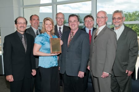
On Friday, September 3, at ANL in Lemont, Illinois, several vendors to this project were acknowledged for their roles, during a presentation made by various key individuals in the project’s start-up and ongoing development. One of these vendors is M-1 Tool Works of McHenry, Illinois, who supplied a variety of machined metal components and assemblies used in the focusing operation on the light beams that create ultra-bright, ultra-short x-ray pulses from a high-energy electron beam. These x-ray pulses are a billion times brighter than the most powerful light source known and are used to capture images of molecules and detail their actions within an atomic structure. The first beam was generated in April, 2009 and the undulator was installed and fully functioning in the Spring of 2010.
Users of this new American technology from every continent are already lining up at SLAC to apply it for the investigation of atoms on various mechanical structures, raw materials, pharmaceuticals, industrial chemicals, military ordnance, space exploration hardware and hundreds of other products. Commercial, institutional, educational, governmental and advanced research concerns are all requesting use of this technology, according to the directors of the project.
M-1 Tool Works, a longtime supplier of precision components to such diverse fields as the aerospace industry, defense, medical, high tech, close tolerance and high reliability commercial industries, had previously done work for Fermilab and Lawrence Livermore National Laboratory. They were called upon by ANL to produce 36 assemblies, each comprising a central assembly and various close tolerance components. The materials used included tool steel, stainless steel, aluminum and specially annealed oxygen-free copper for the particular densities and electrical properties required on this application.
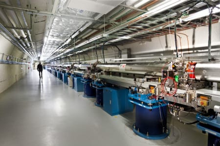
Functionally, the highly collimated electron beam travels through the undulator, where its motion is modified by a series of alternating magnets to create radiation saturation and the coherent alignment structure of the beam. This occurs in a two-mile section of the linear accelerator. First light was generated in April, 2009, light to the instrument was achieved in August of that year and the project was completed for commercial utilization in the summer of 2010. This $415 million project was completed by ANL on time and under budget.
Overall, the undulator section measures 433’ and runs in a 600’ section of the tunnel at SLAC. All the assemblies were built and tested at ANL in Illinois, then transported for assembly and final commissioning at Stanford. A Beam Position Monitor checks the dimension and orientation of the beam to sub-micron levels of accuracy.
For further information on this story, please contact:
M-1 TOOL WORKS INC.
1419 S. Belden Ave.
McHenry, IL 60050-8399
Phone: 815-344-1275
Fax: 815-344-1950
Web: www.m1toolworks.com
Email: ray.lindberg@m1toolworks.com
Attention: Ray Lindberg, Sales Manager
Agency contact:
Tim Daro
Bernard & Company
847-934-4500
tdaro@bernardandcompany.com
CHICAGO — After considerable research and product refinement, as well as extensive field contacts with end-users, Siemens Industry, Inc. introduced today the new 1PH8 family of high-performance induction motor drives and servomotors. Available in a wide power range, from 2.8 kW up to 1340 kW, the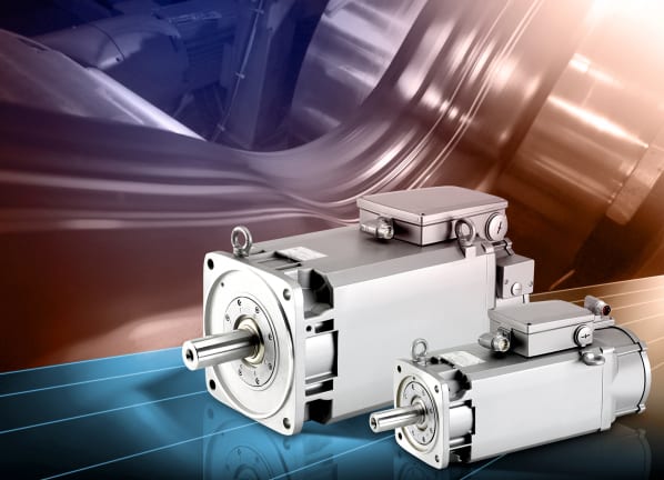
This new line combines induction and high-powered servo technologies to give machine designers and end-users a greater degree of efficiency and more precision in the production process. A single stator and rotor design enables the modular adaptation of the many motor options to provide design flexibility and cost containment.
Designed for the specific performance and environmental requirements of a main spindle on a CNC-equipped machine tool, these new Siemens induction motors have myriad applications in other heavy-duty markets, such as print unit drives on printing presses; rolls and web handling on converting and packaging machinery; crane and hoist elevation; extruders and injection molding machines; metal-forming and welding machinery; assembly line robotic articulation; materials handling gantries and more.
The modular motor platform concept offers designers various options for selecting the optimum unit for an application:
The 1PH8 motor spindle line is fully compatible with the popular Siemens Sinamics® S120 drives platform to achieve faster commissioning and improved control response. All motors in this new family feature the Drive-Cliq® serial interface and electronic nameplate recognition for plug-n-play start-up.
Earlier families of Siemens motor designs can be upgraded to the new 1PH8 series without difficulty, including the 1PH7, 1PL6, 1PH4, 1PM4, 1PM6 and the upper range of the 1FT6.
For more information, visit www.usa.siemens.com/motioncontrol.
For specific product information and inquiries, call (800) 879-8079 ext. Marketing Communications or send an e-mail to: SiemensMTBUMarCom.industry@siemens.com.
Siemens Industry Sector is the world’s leading supplier of innovative and environmentally friendly products, solutions and services for industrial customers. With end-to-end automation technology and industrial software, solid vertical-market expertise, and technology-based services, the sector enhances its customers’ productivity, efficiency and flexibility. With a global workforce of more than 100,000 employees, the Industry Sector comprises the Industry Automation, Drive Technologies and Customer Services Divisions as well as the Metals Technologies Business Unit. For more information, visit http://www.usa.siemens.com/industry.
The Siemens Drive Technologies Division is the world’s leading supplier of products, systems, applications, solutions and services for the entire drive train, with electrical and mechanical components. Drive Technologies serves all vertical markets in the production and process industries as well as the infrastructure/energy segment. With its products and solutions, the division enables its customers to achieve productivity, energy efficiency and reliability. For more information, visit http://www.usa.siemens.com/drivetechnologies.
Continue reading
The unit has 7” insulated walls comprised of 5” of 2300°F ceramic fiber and 2” of 1700°F block insulation. The 6½” floor insulation is made of 4½” of 2300°F firebrick and 2” of 1900°F block insulation. The plate hearth is made of firebrick and is supported by firebrick piers.
Controls onboard No. 871 include a Partlow MRC 7000 recording and programming temperature controller and an electrically-operated vertical lift door.
For more information, please contact: THE GRIEVE CORPORATION, 500 Hart Road, Round Lake, Illinois 60073-2835 USA. Phone: (847) 546-8225. Fax: (847) 546-9210.
Web: www.grievecorp.com. Email: sales@grievecorp.com. Attention: Frank Calabrese.
Continue reading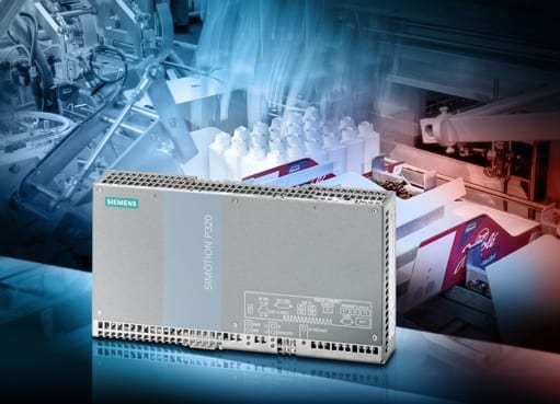
The embedded PC, which features a DDR3 memory and an Intel Core2 processor, is free of wear from moving parts, such as hard disks and fans. This compact motion control system provides maximum flexibility and accommodates centralized or decentralized machine concepts for PC-based applications or for applications that require a compact size.
It is designed for many different motion control applications with its multiple onboard interfaces. They support communication over Profinet, the open industrial Ethernet standard, as well as Ethernet interfaces that run at 10 / 100 / 1000 megabit speeds. Four USB interfaces make it simple to connect a keyboard, USB stick, printer or other devices. A DVI port rounds out the links so users can attach a display or monitor. The Simotion P320-3 can also be used in a “headless” configuration without a display, monitor or front panel.
LEDs on the front indicate the operating states, making self-diagnosis easy. The integrated power supply bridges temporary power failures. In the buffered SRAM memory, the process data is saved securely even in the event of a sudden voltage drop. Monitoring functions for the batteries, temperature and program execution are also included. The Windows Embedded Standard 2009 operating system, which increases the reliability of the system, is pre-installed. Additionally, the Simotion runtime system comes installed on the Simotion P320-3.
Additional information is available online at: www.usa.siemens.com/motioncontrol.
For specific product information and inquiries, call (800) 879-8079 ext. Marketing Communications or send an e-mail to: SiemensMTBUMarCom.industry@siemens.com.
Siemens Industry Sector is the world’s leading supplier of innovative and environmentally friendly products, solutions and services for industrial customers. With end-to-end automation technology and industrial software, solid vertical-market expertise, and technology-based services, the sector enhances its customers’ productivity, efficiency and flexibility. With a global workforce of more than 100,000 employees, the Industry Sector comprises the Industry Automation, Drive Technologies and Customer Services Divisions as well as the Metals Technologies Business Unit. For more information, visit http://www.usa.siemens.com/industry.
The Siemens Drive Technologies Division is the world’s leading supplier of products, systems, applications, solutions and services for the entire drive train, with electrical and mechanical components. Drive Technologies serves all vertical markets in the production and process industries as well as the infrastructure/energy segment. With its products and solutions, the division enables its customers to achieve productivity, energy efficiency and reliability. For more information, visit http://www.usa.siemens.com/drivetechnologies.
Continue reading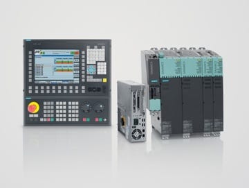
Offered to customers as a standard solution, Zoller has written an interface to connect TDI to the company’s presetter, enabling data to be brought directly into the Siemens numerical control. Zoller boasts accuracy on its presetters to two thousandths of a millimeter (0.002mm) or less than eight millionths of an inch (0.00008in).
By utilizing TDI and a Zoller presetter, a machine tool end-user benefits in many ways, including faster access to tool data with no manual entry of values required. All tool data are transferred to the CNC by an automatic link in the presetter, resulting in significant cost-, time- and operator action savings. In addition, the user develops an increased understanding of tool life and tool wear patterns on various operations in the shop. The Zoller presetter writes data directly onto an RFID chip, making transfer to TDI onboard the Siemens CNC is simple and easy. Lastly, an end-user can maintain a central server that indicates the location of any tool in the shop or factory, as well as track the status of the next tool needed to perform an upcoming operation.
Included in the Siemens TDI suite are the following:
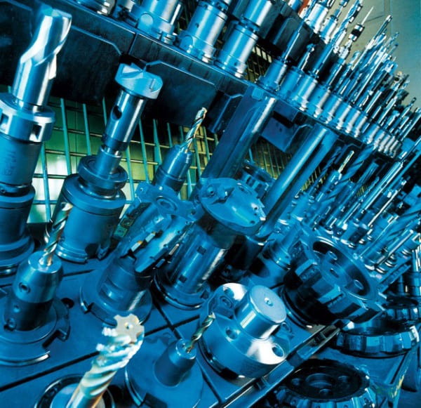
For specific product information and inquiries, call (800) 879-8079 ext. Marketing Communications or send an e-mail to: SiemensMTBUMarCom.industry@siemens.com.
Continue reading
ENERGY MANAGEMENT CONSIDERATIONS WITH TODAY’S DRIVE SYSTEMS
It’s a process, not a product; multiple drive factorscontribute to system energy efficiency
by John Krasnokutsky, Siemens Industry, Inc., Marketing Manager, Motion Control Business
Energy Monitoring Equipment Selection and Optimization (Mechatronics / Parameterization)
Hardware: Common DC Bus / Infeed / Regeneration
While it is valid to state that energy efficiency is defined as the same level of production being achieved at an overall lower energy cost, it is equally important for today’s machine builders and automation engineers alike to remember than an energy-efficient system can actually translate into higher productivity. This is achievable through a comprehensive approach to energy management.
It is a fact that most of the energy loss in a system occurs in three areas, namely, the generation, distribution and conversion of energy into useful work, the last being accomplished through heat exchangers, pumps, motors and drives. This paper will concentrate on the last product group, as it is also a fact that over 25% of all electricity consumed in America is used on industrial electric motor-driven systems. Electric motors represent 65% of the power demand in American industry and, owing to the inefficiency of most motor control systems, the potential for energy savings in an industrial facility can approach 70% for any process where electric motor power is employed.
That said, energy management is a process, rather than a product or series of products installed on a machine, or inline, to achieve a basic energy saving of kW hour consumption. This process must be ongoing and perpetual, meaning that any defined goal should be viewed as a momentary metric of achievement, rather than a final end. While any vendor, including our company, can supply the right products and support services to hit a target mark of energy savings, the mindset of the customer is key in keeping the process recurrent. This ensures a continual increase in the productivity levels achieved, defined as a factor of the energy consumed. In many ways, it can be viewed in the same manner as an ongoing, effective but constantly evolving quality management system at your company.
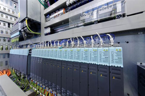
First, energy monitoring systems must be in place to effectively determine the current consumption. These can include, but are certainly not limited to, energy consumption displays, infeed/supply monitoring devices, power factor meters and more. Next, the proper calculation tools are needed to properly evaluate the life cycle costs of any investment. These tools can be as simple as a motor sizing chart or the software programs used to parameterize drives. However, a more formal mechatronics protocol may be beneficial to your operation. In this scenario, a thorough evaluation of both mechanical and electrical/electronic influences on your system, be it a machine or a process line, is conducted. The results can often open the eyes of machine designers, process engineers and system integrators alike. To realize the benefits this analysis the proper products and system solutions must be implemented.
This is where a competent supplier can be an effective partner for your operation. For example, the solution you need might involve a vector drive that utilizes an energy optimization function to enhance the efficiency of the motor during partial load operations. In a system with multiple motors, energy savings might be realized to a substantial degree by the use of a drive unit with a common DC bus. The designer can also select the most appropriate infeed solution for the machine, pump or process operation, given the particulars of performance and required output. This may include an appropriately sized infeed unit with regenerative capability, the ability to put unused or braking energy back on the incoming power line.
Some applications may allow the use of high efficiency standard induction motors and, in the process, realize a potential savings of 1-3%. The use of frequency converters (VFD) for speed control might raise this to an 8-10% savings. VFDs have myriad applications throughout industry on fans, pumps, blowers and compressors, as well as in wasted energy recovery on cyclical acc/dec and regeneration on lost braking energy applications.
Optimizing your entire system through mechatronic analysis of the machine or process design, can result in a potential savings of 15-20% by the avoidance of over dimensioning of motors, plus partial load optimization by means of energy-related flow control. This analysis may also point to the ability to use controlled energy infeed and recovery.
In order to determine the true efficiency of any drive system, it is necessary to demonstrate the amount of energy required by its power components and a corresponding examination of how the system uses energy. How different drive concepts used on the same system under identical power load must also be considered. This latter exercise might look into partial load efficiencies with various motor and drive combinations, straight comparisons betweens synchronous servo vs. asynchronous induction motors or direct drive vs. motor/gearbox combinations, drives with braking components vs. regenerative drive technology, as well as solutions with single vs. multi-drive, common DC bus solutions.
A corollary to this discussion should also include a review of potential hydraulic/pneumatic component change outs in certain applications where replacement with an integrated package of motion control and PLC technology might better resolve closed loop pressure control of axes, for example. Fewer components and their related power consumption can lead to overall system productivity improvements, as well as ongoing enhanced energy efficiencies. Reduced programming, diagnostic and commissioning times can also flow from such an approach, providing even more opportunities for overall machine or process improvements. Tracking the energy efficiency of such a system may seem problematic at first, but here again today’s sophisticated mechatronic and virtual production protocols can be utilized to validate the real-world performance characteristics of such designs, far in advance of their implementation.
As the emergence of new technologies has impacted many of the products used in energy-efficient systems, it is equally important to take a more holistic look at operational sequences and the overall integration scheme when designing, retrofitting or rebuilding for improved energy utilization. The results can be many, including precise process and power factor control for optimum energy use and significant cost savings, plus the collateral benefits of lower carbon footprints, reduced maintenance due to decreased mechanical stress and lower total cost of product quality derived from less mechanical wear and better production control.
Author: John Krasnokutsky
Email: john.krasnokutsky@siemens.com
Website: http://www.usa.siemens.com/motioncontrol
Siemens Industry, Inc.
5300 Triangle Parkway
Norcross, GA 30092
For an informative PowerPoint presentation or more information on this subject, call (800) 879-8079 ext. Marketing Communications or send an e-mail to: SiemensMTBUMarCom.industry@siemens.com.
Continue reading
ATLANTA — Siemens announced today the release of the new Simatic® CPU 317TF-2DP controller that combines motion control, safety and standard tasks in a single device. This device is the latest solution in its totally integrated automation portfolio that integrates and combines devices for the plant floor environment, further reducing footprints and improving overall efficiencies.
The Simatic CPU 317TF-2DP controller unites a series of important features that all go together in one device to reduce the wiring, coding and the implementation times. It also benefits users by saving space on the shop floor and reducing overall total cost of ownership.
Possible applications for the new device range from controlled single-axis positioning to complex, synchronized sequences of motion, such as geared synchronous motion, curve synchronization or print mark correction. The synchronous axes can be coupled to a virtual master or a real master. For safety-oriented applications, the controller fulfills the rigorous requirements of all the relevant standards, including EN 954-1 up to Cat. 4, IEC 62061 up to SIL 3 and EN ISO 13849-1 up to PL e.
For Siemens PLC users, the Step 7 option package S7-Technology is available to simplify engineering and commissioning. The Step 7 option package, supporting simultaneous processing of up to 64 technology objects, is available to meet engineering requirements for programming and commissioning of all functions. For specific fail-safe applications, the Step 7 option package Distributed Safety offers a set of pre-configured library blocks, including emergency stop, two-hand control, muting and door monitoring. No external safety hardware is required for costly safety precautions at the machine, saving valuable space in the control cabinet.
Centralized and distributed fail-safe I/O and fail-safe drives according to PROFIsafe, the fail-safe communication standard, can be connected to the Simatic CPU 317TF-2DP. The drive safety functions SBC, SLS, SSM, SOS, SS1, SS2 and STO according to PROFIsafe can be used in addition to the familiar safety functions.
PROFIsafe both enhances this controller’s capabilities and value while further simplifying commissioning. In particular, PROFIsafe requires less wiring than other controllers available in the market, making it quicker and easier to set up while reducing the risk of errors through the commissioning process.
For more information, visit www.usa.siemens.com/motioncontrol.
For specific product information and inquiries, call (800) 879-8079 ext. Marketing Communications or send an e-mail to: SiemensMTBUMarCom.industry@siemens.com.
Continue readingSaves time, money and engineering through series of online selections; makes spec writing much easier
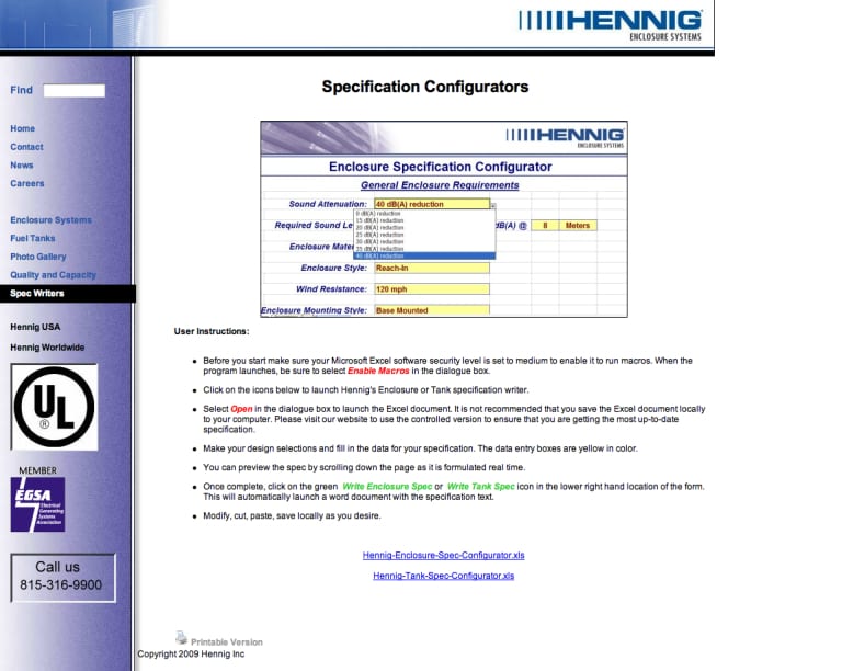
All performance and dimensional requirements are menu-selected, along with all electric, HVAC, exhaust system, roof, door and materials of construction on the enclosure. Likewise, for the sub-base diesel fuel tank, all size and accessory specs are selectable on a downloadable .xls menu for easy completion. Upon completion of the selections, a .doc is generated for the enclosure spec and another for the fuel tank.
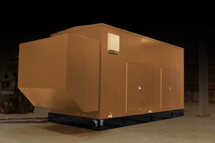
“Through this system, the Hennig enclosure and fuel tank are precisely matched to the generator and the particular conditions of the installation. No settling for less and no need to make a standard product ‘fit’ the requirement. It really is a useful time and money saving tool,” says Robin Moore, the Hennig vice-president for engineering and operations.
Hennig manufactures all enclosures and fuel tanks in its Rockford, Illinois facility, located approximately 90 miles northwest of Chicago. Here, experienced power gen engineers work in concert with the company’s vertically integrated metalworking, fabricating, finishing and test departments to ensure the highest quality and reliable construction of the enclosures and fuel tanks to suit the specification mandated by customers. Hennig then ships the finished units to the construction site, power gen subcontractor or other location with full guarantees of satisfaction, backed by the company’s service and after-sale assistance team.
Hennig currently builds enclosures and fuel tanks to be compatible with CAT, Cummins, Detroit Diesel (MTU Onsite Energy), Kohler and all other leading brands of power generators. The company also works with the power gen distributors, plus design/engineering firms, consulting engineering firms and all levels of the building contractor community. Spec writers at all these types of companies can utilize the new Hennig configurator to save time, money and engineering effort in the construction of gensets.
To learn more about Hennig Enclosure Systems, visit www.hennigenclosuresystems.com or contact:
Tim Waterman
Hennig Inc.
9900 N. Alpine Rd.
Machesney Park, IL 61115
(815) 316-5277
info@hennig.ame.com
www.hennigworldwide.com
—
Hennig, Inc., at www.hennigworldwide.com, has been designing and producing custom machine protection and chip/coolant management products for state-of-the-art machine tools for over 50 years. Hennig products are designed to protect against corrosion, debris and common workplace contaminants. Hennig has manufacturing facilities in the U.S., Germany, Czech Republic, France, Brazil, India, Japan, China and South Korea. Its North American repair centers are located in Machesney Park, Ill.; Chandler, Okla.; Livonia, Mich.; Blue Ash, Ohio; Mexico City, Mexico; and Saltillo, Mexico.
Continue reading