
Contact us today:
(847) 934-4500
tdaro@bernardandcompany.com
Contact us today:
(847) 934-4500
tdaro@bernardandcompany.com
Unique below-ground system at Portland Water Bureau utilizes Lucid Energy power generation, Siemens motors and regenerative drives with natural water flow to create energy; will produce 1.1MW of electricity per year, enough to power 150 homes
Recently, the use of regenerative energy has ramped up quickly in American industry due largely to the advancements in drives technology. Through various mechanical components coupled with regenerative drives, energy can be captured or created and used in three ways. Namely, it can be battery-stored for subsequent use, redirected immediately to other electrical power requirements or fed back to the power company in a contract arrangement, all done without loss of host system performance, mechanical component integrity or safety issues.
Typically, regenerative power is produced by, for example, a motor turning during braking or stopping. What if the motor turned as the result of something other than an electrical power supply?
At the City of Portland (Oregon) Water Bureau, they partnered with a local firm, Lucid Energy, who provided a very unique method of power generation. The renewable energy and smart water management solution used is the supplier’s patented LucidPipe™ Power System, which enables industrial, municipal and agricultural water facilities to generate clean, reliable and low-cost energy from gravity-fed water pipeline and stream flow.

The LucidPipe™ Power System uses a unique lift-based, vertical axis spherical turbine technology to smoothly transfer the kinetic energy of the water flow to rotate the motor shaft without impeding the water flow to any great degree. Photo Credit: Sherri Kaven.
For a recent installation under the road at SW 147th Avenue and Powell Boulevard in Portland, Lucid Energy provided their system, which comprises four 42” lift-based turbines spun by the gravity-fed water flow inside the Portland Water Bureau pipeline. These turbines turn four Siemens torque motors as 50kW generators for a 200kW nameplate capacity project. The electricity generated by this system is captured and fed to the Portland General Electric (PGE) grid by four Siemens regenerative drives. In a 20-year power purchase agreement, this project will generate approximately $2 million in renewable energy capacity, to be used for development, installation and operational maintenance costs.
The project investor, Harbourton Alternative Energy, will share the revenue with the City of Portland and Portland Water Bureau to reduce the cost of water operations. Upon completion of the agreement, Portland Water Bureau has the right to purchase the system and the power produced. Since the pipeline is expected to have a lifespan of over 50 years, this project represents a mutually beneficial arrangement for the investor and the city alike.
Known as the Conduit 3 Hydroelectric Project, this system represents the first venture in the U.S. to secure a 20-year Power Purchase Agreement for renewable energy produced by in-pipe hydropower in a municipal water pipeline.

The installation of the system at SW 147th Avenue and Powell in Portland, Oregon. Photo Credit: Sherri Kaven.
“For the execution of this project, we reached out to Siemens, in tandem with their solution partner in our area, Applied Motion Systems, who wrote the software for the regenerative operational protocols, connecting the hardware to the grid,” according to Lucid Energy’s director of operations, Susan Priddy. In addition to the drives and motors on this project, Siemens also provided the motion controller, transformers, circuit breakers and all power supplies. The master control cabinet is installed underground, in close proximity to the pipeline and the four LucidPipe turbines (shown in photo).
Functionally, the water being fed from reservoirs flows downhill to turn the torque motors into generators, which supply power back onto the Siemens Sinamics S120 drive system, which in turn feeds it to the electrical grid of PGE. The electricity is generated by the water flow with no other power source. The pipeline performance is unaffected and there is no environmental impact. The Lucid Energy system has been tested and certified by NSF International to meet the NSF/ANSI Standard 61 for potable water systems. The LucidPipe system extracts very little head pressure, typically 1-5 PSI, so the turbine units can be installed in sequence without disruption of the water flow. The system does not require installation in a pressure-transient zone or where extreme differential pressures are required.
Lucid Energy developed its patented lift-based, vertical axis spherical turbine technology (shown in photo) at the end of the generator’s flange to maximize the use of the water’s gravitational flow to put work back onto the motor. Units can be installed in 24”-96” diameter pipes. For this project, Lucid Energy was able to use standard motor and drive components that would typically require external power supply to control the motion of a machine, as part of its LucidPipe™ power generation system.
Aesthetically, as a collateral benefit, the entire system detailed here is located underground.
The system was final tested in February 2015 and is producing power to full expectations today. Based on subsequent performance metrics analysis, Portland Water Bureau is considering additional installations of the LucidPipe system.
Ryan Misjan and Steve Schoneger from Siemens, plus Susan Priddy from Lucid Energy and Jennifer Allen Newton from Bluehouse Consulting Group contributed to this story.
See the system in action! http://www.lucidenergy.com/how-it-works/
For more information on this story, please contact:
LUCID ENERGY
2420 NE Sandy Boulevard
Suite 203
Portland, OR 97232
Phone: 503-341-0004
www.lucidenergy.com
Attention: Gregg Semler, President & CEO
Or
SIEMENS
Digital Factory
Factory Automation
5300 Triangle Parkway
Norcross, GA 30092
Phone: 770-871-3848
www.usa.siemens.com/drives
Attention: Sandra Tigert
—
How Regenerative Drives Work
Power regeneration is the process of recovering kinetic energy created by a motor turning during stopping or braking or, as in the situation described in this story, by the natural gravitational motion of water flow, and converting that energy to electricity, then feeding it back onto the grid.
Siemens regenerative active infeed drives, as demonstrated in this story, efficiently return the energy created back into the supply system, rather than losing the energy in the form of heat or inertial load losses. The regenerative operation is combined with power quality management, improving the overall operational system efficiency. By virtually eliminating harmonics and optionally providing power factor control to compensate for poor power factor from other loads, active infeed drives provide more stable operation on the load in weak supply systems with voltage and frequency fluctuations and can actually help stabilize the supply system. Motor performance is also improved significantly with active infeed (also called active front end) regenerative drives technology.
A practical alternative to mechanical braking and non-regen drives systems in the converting, packaging, wireforming and printing industries
by William Gilbert, Industry Business Development Manager,
Converting and Cranes, Motion Control Solutions

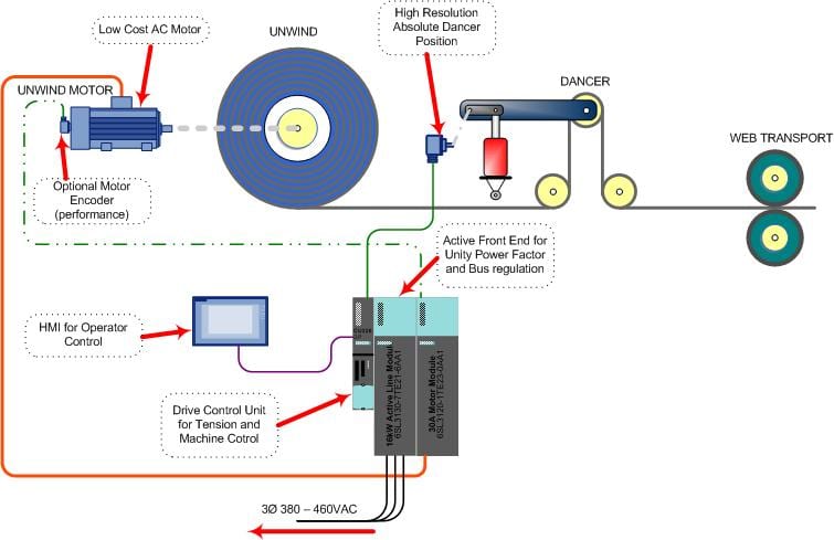
The unwind brake operates much like the brake on a car, with disk, calipers and pads. The tension is linked to a position controller.
During the operation of any converting machine, whether for film, foil, wire, paper or board, plus most large printing presses, rolls of materials are handled by unwinds, often still driven by pneumatically operated braking systems. The traditional tension control system for an unwind stand is a simple mechanical brake. In principal, the unwind brake mechanically operates much like the braking system on your car, with a disk, caliper and pads, but is controlled by a tension sensor linked to a setpoint controller. As the roll unwinds, the tension is maintained by the brake for smooth passage of the material through the dies or rollers, resulting in better package alignment, less wrinkling, better print registration, even more consistent wire dimensioning and other production positives. These mechanical brake unwinds are effective in controlling the tension, but have inherent problems of heat and power loss, plus mechanical wear and constant maintenance needs, substantially impacting machine uptime.
The typical mechanical brake is pneumatically controlled and may utilize several sets of friction pads to control the web tension as the roll dimension decreases. Plus, a reasonable pressure range in many applications might be from 15-90psi or a 6:1 drop, a range significantly less than the core to full roll ratio for most jobs, an obvious inefficiency in operation.
This schematic shows the typical driven unwind system in operation
To affect good tension control on the brake, these friction pad sets need to be manually changed in an out of the brake assembly, depending on the desired operating tension and the roll diameter changes involved. Often, the adjustments are several per roll during this manual changeover. Because the mechanical brake creates the unwind tension through friction, it generates substantial heat and often requires a separately powered fan for cooling to operate effectively. This friction also means the pads are subject to rapid wear, requiring frequent and time-consuming changes or maintenance checks.
For almost a decade now, this old technology has been gradually replaced, though usually in the lower power ranges, by newer precision technology, involving AC motors, drives and electronic loadcells. On converting lines today, a further leap forward is being made with the onset of active front end technology.
With such technology, the operating principle is as follows.

Conventional mechanical brake system
Since the unwind application is regenerative (regen) in nature, a driven unwind needs to return the energy that the mechanical the brake produced as heat back to the AC line. In the past, regen DC drives have been successfully applied as driven unwinds, but DC drive systems are no longer common and even during their prime were very costly. Early in the AC drive technology for these applications, the drives did not have the capability to regenerate the power back to the AC line and, when applied as unwind brakes, required regen resistors to dissipate the tension energy. This was wasteful and costly.
Today’s AC drive systems now have the technology to regenerate the energy back to the AC line just as the DC drive did, but with added benefits to the user and machine designer alike. Sending the tension energy back to the line means power that once was wasted can now be retained, instead of the system producing heat and worn parts. When the drive is equipped with active front end technology, it will return the previously wasted energy with near unity power factors, something not possible for any DC drive system.
Even an open loop AC drive motor combination offers a tension control range far beyond the limits of a pneumatic braking system. Synchronous AC motors can offer precision open loop torque control without a tension sensor, thereby saving further cost and inventory. Today’s highly accurate tension control systems can be designed with high resolution (sin/cos) feedback encoders on both the unwind motor and dancer position feedback. Additionally, in more advanced active front end designs, the regen capability of the drive can actually assist in the increase of stopping times and tension control regulation, owing to the four quadrant control, i.e., the motor can sink or supply current to the motor in both directions.

Driven unwind with AC regen motor, drive
AC regen drive systems can also offer today’s machine designer software configurations with a wider range of control flexibility. They can be configured to operate in the most basic mode with no motor encoder or with tension feedback to system configurations, utilizing either dancer position sensors or loadcells. Alternatively, they can function as a programmable logic controller (PLC), controlling the machine functions on the unwind, while also connecting directly to a human-machine interface (HMI) panel. In most converting, packaging and printing applications, the dancer position sensor can be used to calculate the starting diameter of a roll, eliminating additional diameter sensors and the possibility of operator error in the roll diameter input. Further enhancements for unwind spindle motion such as jog for threading have also emerged for operator convenience through active front end technology.
Beyond the obvious cost savings of pad replacements on mechanical braking systems, AC motors are virtually maintenance free by comparison to DC motors, as AC motors have no brushes, do not require controller contactors to reverse direction of motor rotation or have commutators. Fewer moving parts invariably means less motor maintenance, for additional cost and time savings.
In the most advanced systems, common DC bus regulation, energy-monitoring devices for near unity power and, through the use of mechatronic services often provided by the manufacturers, “turn off” parameters in vector drives are possible. Mechatronic services can also be utilized for the proper tuning of these drives onsite or during machine build. For designers, such services further assist in the proper sizing of motors, based on the mechanical and electrical forces generated by machine operation or computerized simulation of it.
This combination of improved operation, reduced maintenance, motor power savings and conservation of nearly all energy within the system make AC regen drives with active front end technology a decided advantage for machine designers and end users of converting, packaging, printing, wireforming and other roll-fed machinery, where driven unwinds can be implemented.
For more information on regenerative drive motors and systems, please contact:
For product information and inquiries, call +1 800 879 8079 ext. Marketing Communications or e-mail SiemensMTBUMarCom.industry@siemens.com.
Continue reading